Send the basic requirement now. Drawings, BOMs and specifications help us respond more precisely.
How to Specify a Cold Plate for IGBT and Power Electronics
Updated 16 October 2026
A cold plate for an IGBT, inverter or other power-electronics assembly is defined by the heat-source map and mounting interface as much as by its external dimensions. A useful specification connects the semiconductor layout, coolant circuit and inspection plan before the channel design is released.
Start with the heat-source map
Identify each heat source, its footprint, expected load and duty cycle. Record the maximum permitted component temperature and the temperature available at the coolant inlet. The plate should place effective cooling under the real heat sources while preserving the mounting and service features of the assembly.
Component locations and contact footprints
Continuous and peak heat load
Temperature limits and ambient conditions
Mounting holes, fasteners and interface material
Clearances for busbars, sensors and covers
Describe the coolant conditions, not only the flow rate
State the coolant composition, inlet temperature range, available flow, pressure budget and connection arrangement. Flow rate alone does not establish cooling performance. Channel length, cross-section, distribution, heat-source position and the rest of the circuit affect both heat transfer and pressure drop.
Make the contact interface part of the drawing review
Flatness, surface finish, hole position and mounting pressure influence thermal contact. Define the critical contact areas and the dimensions that cannot change. If a thermal interface material is used, identify its thickness or installation condition where that information is part of the acceptance requirement.
Choose the construction after the requirements are clear
Embedded tube, brazed, machined-channel and friction-stir-welded routes solve different combinations of geometry, sealing, flow and production requirements. The correct route is project-specific. See the FSW liquid cold plate example and the thermal manufacturing page for a starting point.
Define sample acceptance before production
Agree the drawing revision, critical dimensions, pressure or leak method, flow conditions, cleanliness requirements and thermal validation responsibility. Include the quantity and documentation required with delivery. For a project review, use the OEM/ODM route or send your power-electronics requirements.
Updated 16 October 2026
The choice between an air-cooled heat sink and a liquid cold plate should follow the equipment constraints, not a preference for one component type. Heat load, available airflow, allowable temperature, installation space and maintenance conditions all change the practical answer.
When an air-cooled heat sink is the better starting point
A custom heat sink is often worth reviewing when the equipment has usable airflow, a relatively accessible mounting envelope and no requirement for a pumped coolant loop. The design still needs more than a nominal wattage: the heat-source footprint, contact surface, fin direction, fan position and surrounding clearance determine whether air can remove heat effectively.
Heat load and duty cycle at the actual operating point
Airflow direction, available flow and fan or duct constraints
Base thickness, contact flatness and mounting pressure
Fin height, pitch, length and service clearance
Surface finish, corrosion environment and production quantity
When liquid cooling deserves a closer review
A liquid cold plate can be considered when heat density is high, air is insufficient, the enclosure is compact or the equipment already has a coolant loop. It should be evaluated as part of that loop. Pump capacity, heat exchanger performance, coolant compatibility, connection interfaces and pressure drop are part of the decision.
Two designs can show different results because they were tested with different heat-source footprints, airflow, coolant temperature, mounting pressure or acceptance methods. Ask which test condition is being compared and whether it represents the installed equipment. A result without the boundary conditions is not enough to release a design.
What to decide before requesting a quotation
Mark the heat-source location, the installation envelope and the interfaces that cannot change. Add the target temperature, airflow or coolant conditions, quantity and required inspection evidence. If the route is still open, use the OEM/ODM development route to review both heat-sink and cold-plate options, or send the requirement to SUNENG.
Updated 16 October 2026
A heat sink is selected by the heat source, airflow, available space, mounting interface and production requirement. Fin appearance alone does not show whether the assembly will keep the component within its operating limit.
Start with the thermal boundary
Provide the heat load, duty cycle, allowable component temperature, ambient temperature and the thermal interface between the component and the sink. For forced air, include airflow direction, velocity or fan data and the permitted pressure drop. For natural convection, installation orientation and clearance around the fins become important.
Choose a construction that fits the requirement
Extruded and skived fin sinks can suit different combinations of standard geometry, fin density and production quantity. Bonded or assembled fins may be considered where the envelope or fin arrangement needs another route. CNC machining can add mounting features, pockets, interfaces and small-batch geometry. The final process should follow the drawing, quantity and acceptance requirements.
Check the mechanical details
Component footprint and hole pattern
Base thickness and contact flatness
Fin height, spacing and cleaning access
Fastener, clip, spring or adhesive interface
Envelope, weight and clearance to neighbouring parts
Ask how the result will be verified
Dimensional inspection confirms whether the part follows the drawing. Thermal testing requires a defined heat input, interface material, airflow, ambient condition and measurement method. If the sink is part of a larger enclosure, the test setup should represent the installation closely enough to support the decision.
Make a useful custom enquiry
Send the component drawing, heat load, ambient condition, airflow information, mounting details, material preference, quantity and surface requirements. Mark which values are fixed and which can change. SUNENG can review heat sinks and liquid cold plates through the same thermal manufacturing route, with development support available through OEM/ODM.
Embedded tube, brazed and friction-stir-welded cold plates solve different manufacturing problems. Comparing them by product name alone hides the decisions that affect flow, sealing, flatness, interfaces and production quantity.
Embedded tube cold plates
An embedded tube construction uses a metal base and a formed tube route beneath the component contact area. It can be suitable when the required channel path, tube connections and thermal interface can be accommodated by the plate geometry. Review tube material, bend radius, groove design, joining method, surface machining and connection details together.
Brazed cold plates
Brazed constructions join prepared parts through a brazing process. They can support internal passages and compact layouts, but the joint design, cleaning, furnace or process conditions and leak verification need to be defined for the project. A drawing should identify the sealing boundary and any areas that cannot accept distortion or residue.
Friction stir welded cold plates
Friction stir welding can join plate sections around a machined channel or internal cavity. It may be considered for larger plates or designs where the welded boundary and structural strength are important. The joint path, tool access, start and stop areas, surface finishing and inspection method should be reviewed before the route is selected.
Compare the routes against the real constraints
Thermal: heat load, contact area, temperature distribution and coolant path.
Mechanical: plate size, flatness, mounting holes, ports, vibration and service access.
Production: prototype quantity, repeat quantity, tooling, machining time and process control.
Evidence: drawing revision, dimensional records and the testing available for the confirmed supply.
Choose after the requirements are visible
The lowest initial price is not automatically the lowest project cost. A route that requires fewer changes after sample approval may be better for the total schedule. SUNENG can review the application, drawing, installation envelope and quantity before discussing a suitable manufacturing route. Start with the thermal manufacturing page, review the OEM/ODM development route or send the technical requirement.
Updated 16 October 2026
A liquid cold plate should be selected from the heat source, installation envelope and coolant loop together. Plate size alone does not tell you whether the solution will meet the temperature, flow or pressure-drop limits of industrial power equipment.
Start with the heat and mechanical envelope
Record the heat load, the number and location of heat sources, the permitted component temperature and the available mounting area. The plate also needs to fit around fasteners, busbars, sensors, covers and service clearances. A cold plate that performs well in isolation can still fail to fit the finished assembly.
Heat load and duty cycle
Heat-source footprint and mounting pattern
Maximum plate length, width and thickness
Flatness and surface-finish requirements at the contact face
Inlet, outlet and hose or fitting constraints
Match the construction to the project
An embedded tube cold plate can be a practical route when the required flow path and plate geometry are compatible with tube forming and groove assembly. A machined-channel plate may be considered when the channel layout or mounting features need more direct machining. Brazed and friction-stir-welded constructions can suit other geometries and sealing requirements. The right choice depends on thermal, mechanical, production and validation requirements together.
Check the coolant loop before fixing the channel design
Provide the coolant type, operating temperature, available flow, pump pressure and acceptable pressure drop. The channel route should be reviewed with the pump and heat exchanger rather than treated as a separate drawing exercise. Coolant compatibility, corrosion risk, trapped air and drainability may also affect the material and connection design.
Define how the sample will be accepted
Before sampling, agree which dimensions, interfaces and performance checks are critical. Depending on the project, the review may include dimensional inspection, surface flatness, pressure or leak checks, flow and pressure-drop checks, cleanliness and thermal testing. The method, test condition and pass criteria must be confirmed for the actual requirement.
What to send for a useful review
Send the drawing or 3D model if available, heat-source map, coolant information, mounting details, quantity, target schedule and required evidence. If the drawing is incomplete, mark the dimensions that cannot change and identify the open decisions. Use the OEM/ODM development route or send the requirement to SUNENG.
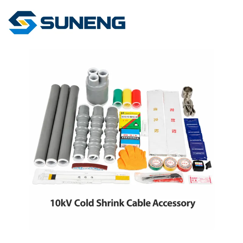
An enquiry that says “10 kV, three-core, 240 mm²” gives a supplier a useful starting point. It still leaves several questions open: the cable insulation diameter, screen and armour construction, installation location, equipment interface and which components the kit must include. Resolving these before ordering reduces the risk of discovering a mismatch during a shutdown.
Start by identifying the job: a cable termination at equipment, a straight-through joint, or environmental sealing around an existing connection. Those functions require different components. A cold-shrink sealing sleeve alone should not be specified as a complete medium-voltage termination.
Product reference for the selection discussion; confirm the exact model, drawing and application before ordering.
Read the cable construction before choosing the kit
Ask for the cable manufacturer’s datasheet, the marking on the cable and a construction drawing. Record its voltage designation exactly as stated, including U0/U (Um) where used. Confirm the system requirements separately with the project engineer. A shortened market description such as “10 kV cable” may omit information needed to select the accessory.
Keep conductor cross-section, insulation diameter and overall cable diameter in separate fields. The conductor fits the terminal or connector; the accessory body fits the relevant prepared cable layers; outer sealing components fit another part of the cable. Substituting one diameter for another can lead to a kit that appears correct in a catalogue but is unsuitable for the actual cable.
Information to send
Details to identify
What the supplier should confirm
Cable identity
Manufacturer, designation, voltage rating, core count and insulation material.
Applicable kit and cable constructions covered.
Cable dimensions
Conductor construction, insulation diameter, oversheath diameter and drawing tolerances.
Dimensional ranges for the accessory and sealing parts.
Screen and armour
Metallic screen type, armour, sheath and required bonding arrangement.
Earthing components and connection method included in the proposal.
Location and interface
Indoor/outdoor use, exposure, clearances, terminal palm or equipment bushing drawing.
Accessory configuration, terminal interface and installation space.
Site method
Available working space, tools, installer experience and restrictions on heating.
Installation procedure, equipment and preparation requirements.
Compare cold-shrink and heat-shrink against the site
Cold-shrink components are typically supplied expanded on a removable support. Removing that support allows the component to recover onto the cable. This avoids a heating step for that component, but cable preparation, dimensional compatibility and installation sequence still determine the result. Confirm storage conditions and shelf life for the specific kit, especially when delivery and installation are months apart.
Heat-shrink components recover when heated according to their installation instructions. Check whether the site permits the specified heating equipment, how the installer will access the component and whether other nearby materials affect the work method. A lower kit price may be offset by site equipment, permits or additional labour; obtain those costs from the contractor before comparing the complete installed scope.
For either route, ask for the instructions for the actual kit. Agree who supplies conductor connectors, crimping tools, preparation tools and any consumables. A familiarity with one manufacturer’s assembly does not establish the preparation dimensions of another.
Confirm exactly what arrives in the box
Request a component list tied to the kit code. Have the supplier mark the following as included, separately quoted, or provided by the installer:
Termination or joint bodies, stress-control components and sealing parts.
Breakout and phase-identification components where applicable.
Terminals or joint connectors, with conductor range and equipment interface.
Screen/armour continuity and earthing components required by the approved arrangement.
Installation instructions, special tools, consumables and any specified test documents.
Resolve terminal selection at the same time. A correctly selected accessory cannot compensate for a lug that does not accept the cable or fit the equipment. Use the cable-to-lug compatibility checklist to confirm those interfaces.
Before releasing the order
Compare the offered kit code with the cable datasheet, installation drawing and component list. Record any deviation and obtain project acceptance before purchasing. For a repeat order, check whether the cable manufacturer, insulation diameter or equipment connection has changed since the previous delivery.
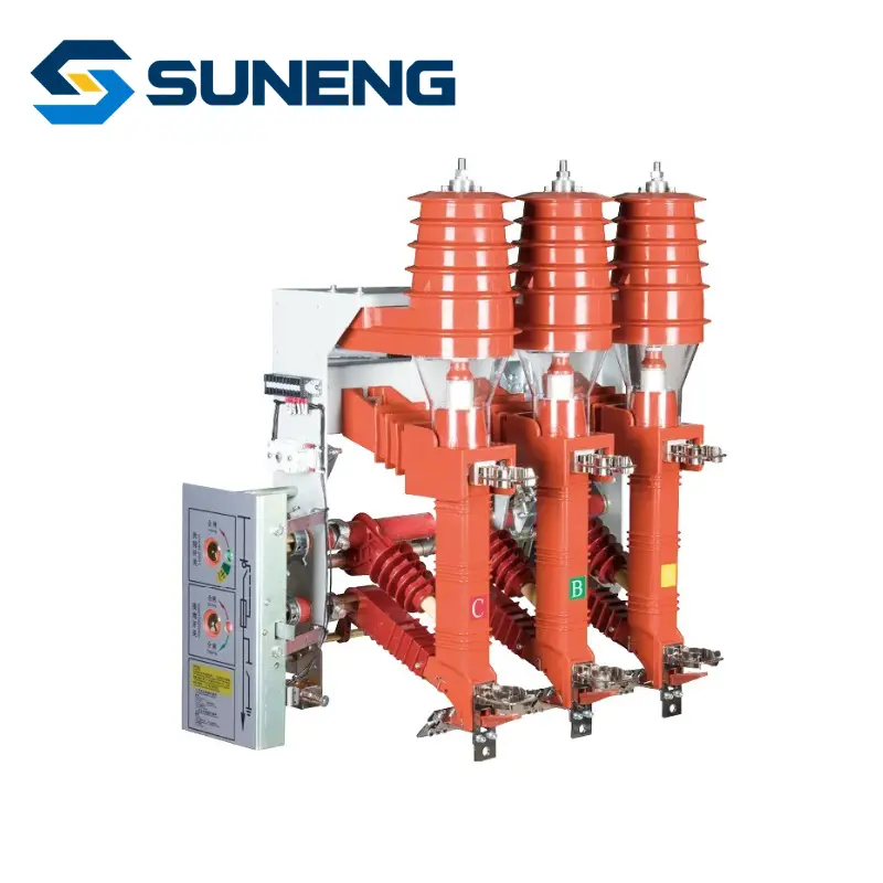
A replacement switchgear device must perform the duty required by the circuit and work with the panel’s mechanism, controls and interlocks. Matching the voltage, current and mounting holes is only the start. Before requesting a substitute, identify whether the component is a circuit breaker, a load-break switch, a switch-fuse combination or a disconnector.
Send a single-line diagram and the existing device reference with the enquiry. Include the panel manufacturer and model if available. The equipment design establishes which switching, protection and isolation functions the device must provide.
Product reference for the selection discussion; confirm the exact model, drawing and application before ordering.
Start with the function in the circuit
Device
Function to establish
Key replacement question
Circuit breaker
Switching normal current and interrupting specified fault current within its ratings.
Do interrupting duty, operating sequence and protection/control interfaces match?
Load-break switch
Switching the load duties for which it is rated.
Which making and breaking duties are specified, and how is fault protection provided?
Switch-fuse combination
Coordinated switching and fuse protection in the defined assembly.
Are the fuse selection, striker/trip arrangement and combination ratings confirmed?
Disconnector
Providing the specified isolation function, with any switching duty limited to its declared capability.
Does the operating scheme prevent use beyond that switching capability?
A load-break switch with a making rating is not automatically a circuit breaker capable of interrupting the same fault current. Similarly, a vacuum interrupter in a device does not by itself identify the complete device’s function. Read the ratings and assembly description together.
Write the ratings with their meaning attached
Record rated voltage, insulation requirements, normal current and the relevant making, breaking or short-time withstand duties separately. Preserve the specified durations and operating sequences. A quotation that contains an unexplained current value in kA leaves too much open for a replacement decision.
Ask for the standard and edition applicable to the particular device and assembly, where specified by the project. The relevant IEC 62271 requirements differ between device types. A test record for a standalone component does not by itself establish the performance of a modified complete panel.
Check the control circuit before the order
Provide the control schematic and identify AC or DC supply voltage for each function. Record the closing and trip releases, charging motor, auxiliary contacts, position indication and connector pinout. Include any undervoltage release or other option fitted to the existing device.
Which signals command closing and tripping, and which signals confirm position?
Which contacts are required by the protection, remote-control and indication circuits?
Which mechanical and electrical interlocks control operation?
Which connectors, terminal numbers and cable lengths must match the existing panel?
Mark each answer on a comparison drawing. Describing both devices as “motor-operated” does not establish that their power supplies, wiring or control logic correspond.
Check the complete installation envelope
Measure mounting centres, phase spacing, terminal locations and operating-shaft position. Include mechanism travel, service access and the clearances required by the approved panel design. A photo from the front can conceal a different shaft location or terminal depth.
For a withdrawable device, include the truck, racking, contact and position-interlock interfaces. For fixed equipment, identify all mating conductors and supports. Ask the panel designer to review any change affecting clearances, barriers, protection or interlocking before accepting a substitute.
Define a clear purchase and approval boundary
State whether you require a complete ring main unit, an assembled functional unit or an individual component. List the mechanism, fuses where applicable, control accessories, connection hardware and documents expected in the supply. Equipment shown together in a photograph may be quoted separately.
Use an approval record containing the original and proposed models, duty comparison, interface drawings, control schematic, deviations and agreed checks. Arrange sample or first-unit fit checks where appropriate, followed by the assembly verification required by the project. Physical fit is one part of the approval.
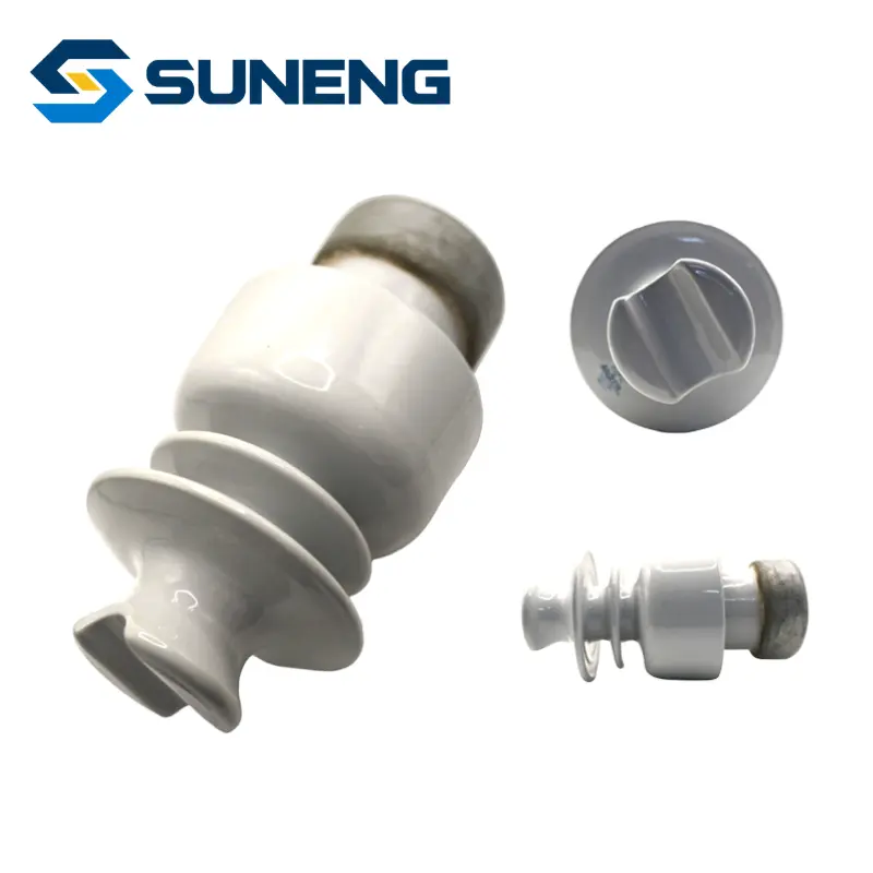
A replacement insulator should not be approved from the voltage label alone. A 33 kV candidate may still differ in creepage distance, mechanical class, connection geometry and environmental suitability. The safest comparison starts with the existing installation and the duty it must continue to perform.
Use this guide when an original insulator is unavailable, a project is changing suppliers, or a buyer needs an equivalent for an existing line. It is a comparison framework, not an automatic substitution approval.
24PC(600) line-post insulator reference. The products linked below serve different arrangements; they are not interchangeable replacements.
Separate the electrical and mechanical questions
Record the system voltage and insulation requirements separately from the mechanical load and interface. The voltage marking identifies only one part of the application. A candidate must also fit the conductor arrangement, hardware and support structure without changing the approved clearances or load path.
Check first
What the buyer should send
What must be confirmed
Electrical duty
System voltage, frequency, insulation level and project specification.
Candidate ratings and the design basis used for the offer.
Creepage and clearance
Pollution exposure, altitude, site conditions and existing dimensions.
Required creepage, external clearances and application fit.
Mechanical load
Vertical, longitudinal and transverse loads or the design load case.
Mechanical class, safety factors and load direction.
Connection geometry
Base, pin, cap, bolt pattern, conductor clamp and hardware drawings.
Hole centres, thread or pin dimensions, stack height and access.
Environment
Indoor or outdoor use, altitude, dust, salt, ice, wind and temperature.
Material, profile and protection suitable for the actual site.
Evidence
Existing nameplate, drawings, photographs and required documents.
Product data, drawings, test records and acceptance items.
Measure the old part before asking for an equivalent
Photographs help identify the assembly but rarely capture the dimensions that determine fit. Measure the overall height, mounting centres, connection points, hardware envelope and the position of the conductor or fitting. Mark each measurement on a sketch and state which dimensions are fixed by the existing structure.
For a line-post or pin-type arrangement, include the mounting interface and the top fitting. For a suspension or strain arrangement, include the attachment hardware, load direction and clearance envelope under the normal and abnormal load cases. If the insulator is part of a metal fitting assembly, send the mating fitting drawing as well as the insulator reference.
Do not treat material as a simple upgrade decision
Porcelain and composite insulators can serve different applications and may use different interfaces, profiles and inspection requirements. The question is not whether one material is universally better. Compare the actual pollution, mechanical, installation and maintenance conditions with the candidate’s documented design.
A similar-looking body is not enough evidence of equivalence. Changes in shed profile, end fittings, housing length or hardware can change the installation envelope even when the voltage label appears familiar.
Review the replacement as a system
Match the conductor hardware, clamp, bolt set and attachment fitting to the proposed insulator.
Confirm phase-to-earth and phase-to-phase clearances after installation, not only catalogue dimensions.
Check whether the existing structure, bracket or cross-arm accepts the new load path and hardware.
Record the drawing revision and candidate model used for the comparison.
Obtain project-engineer approval for any deviation from the original arrangement before ordering.
When the catalogue does not give an exact replacement
SUNENG can review porcelain, composite and associated line-hardware requirements together. If no catalogue model matches, send the existing dimensions, load case, site environment, voltage, quantity and photographs of the mating assembly. A replacement drawing or custom connection can then be reviewed before production.
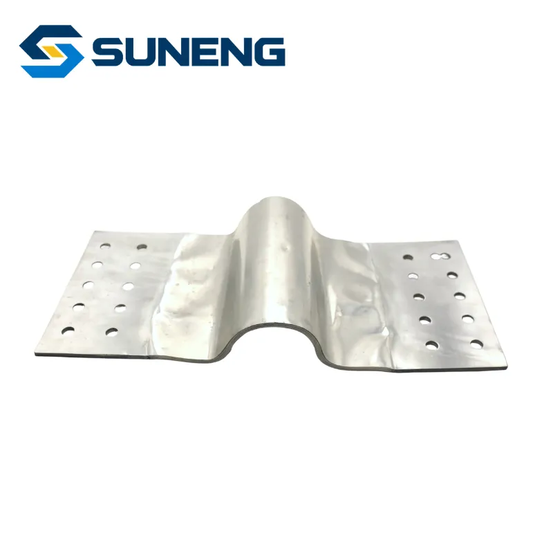
A flexible busbar or soft connection is not selected by copper cross-section alone. Current duty, connection faces, heat dissipation, available space and the way the connection moves all affect the correct design. A part can carry the nominal current and still be wrong for the enclosure or installation sequence.
Use this checklist for transformer, switchgear and distribution-panel connections where a rigid bar would create alignment or vibration problems. The final design should be checked against the equipment arrangement and project requirements.
Product reference for the selection discussion; confirm the exact model, drawing and application before ordering.
Define the connection duty before choosing the form
State whether the connection carries continuous current, short-duration current, or both. Identify whether it absorbs assembly tolerance, vibration, thermal movement or repeated movement. A static flexible link and a repeatedly flexed link should not be described as the same requirement.
Input
Details to provide
Design response to confirm
Electrical duty
Continuous current, short-time duty, system voltage and connection arrangement.
Conductor section, layer or braid arrangement, insulation and stated acceptance basis.
Terminal palms, finish, hardware envelope and interface drawing.
Space
Installed length, width, bend radius, nearby barriers and service clearances.
Finished dimensions, bend direction, movement allowance and install sequence.
Thermal environment
Ambient conditions, enclosure ventilation, nearby heat sources and duty cycle.
Temperature-rise review under the stated arrangement.
Movement
Static tolerance, vibration, thermal movement or repeated flexing.
Flexible form, length, support and expected movement cycle.
Inspection
Required dimensions, finish, material records and electrical or mechanical checks.
Sample, first-article and production acceptance plan.
Check the envelope in three dimensions
Provide the distance between mating faces, the angle between them and the space available around the connection. A two-dimensional length is often insufficient because the link may need to clear an enclosure wall, insulating support, cable termination or moving mechanism.
Send a marked-up photograph or 3D model when possible. Show the installed position, bolt access and the direction in which the link must bend. If the connection is between a transformer and switchgear, include both terminal drawings rather than asking the supplier to infer the arrangement from equipment names.
Do not hide heat in the current number
Temperature rise depends on the complete connection: conductor form, contact surfaces, fasteners, enclosure, airflow and nearby heat sources. Ask the supplier to state the arrangement used for any temperature or current evidence. A value from a different length, terminal, enclosure or mounting condition is not automatically transferable.
For layered copper links, check layer count, separation, edge treatment and the way the layers are terminated. For braided or laminated links, check finished width, thickness, flexibility and bend direction. The product name alone does not freeze these details.
Approve the sample against the installed interfaces
Verify hole centres, hole diameter, palm orientation and finished length.
Place the sample in the actual or representative equipment envelope before freezing the drawing.
Check bolt access, washer clearance, insulation distance and the intended tightening procedure.
Record the movement or vibration requirement and repeated cycles if relevant.
Separate appearance and fit approval from electrical, thermal and mechanical acceptance.
Use a custom drawing when the standard part is close but not right
SUNENG supplies flexible busbar connections and can review non-standard length, width, hole pattern, bend angle, insulation and terminal interfaces. Send the equipment drawings, current duty, space envelope, quantity and required documents so the proposed soft connection is designed around the real installation.
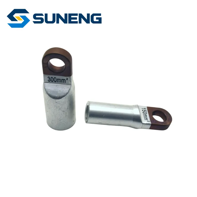
“240 mm² cable” and “240 mm² lug” are not a complete compatibility specification. The cable’s conductor construction, the connector’s accepted conductor range, the equipment interface and the approved installation system all need to agree before an order is released.
The number in this example is an enquiry scenario, not a claim that a particular 240 mm² product is defective. The same review applies to other conductor sizes. This article is a procurement checklist; installation must follow the selected connector’s instructions and qualified site procedures.
Bimetallic terminal product reference. Confirm the selected size and drawing; this image is not a 240 mm² dimensional specification.
Start with the conductor, not the outside of the cable
Request the cable manufacturer’s datasheet and construction designation. Keep overall cable diameter, insulation diameter and conductor diameter in separate fields: they describe different interfaces. For a compression barrel, the relevant conductor details cannot be replaced by a measurement over the insulation.
Record whether the conductor is copper or aluminium, its nominal cross-section, construction or class, shape and whether it is compacted. Ask the connector supplier to confirm suitability for that identified conductor. Do not assume a connector approved for one construction accepts every conductor carrying the same cross-section label.
A fit check has four parts
Check
Buyer provides
Supplier confirms
Conductor
Material, construction designation, nominal size, shape and available dimensional data.
Accepted conductor type and size range for the exact connector.
Barrel
Conductor dimensions and any restrictions on available stripping or insertion space.
Barrel drawing, insertion requirements and connector-specific preparation instructions.
Equipment
Stud or bolt arrangement, hole centres, mating material, palm envelope and cable approach.
Hole pattern, palm width and thickness, angle, finish and installation clearance.
Installation
Available tool and die identification and the proposed site method.
Approved tool/die system, compression sequence and inspection requirements.
If the conductor will not enter the barrel
Stop and compare the cable designation with the connector drawing and accepted conductor list. Check whether the delivered connector is the ordered variant. Give the supplier the observed dimensions and photographs of an uninstalled sample; do not improvise a conversion by removing strands or machining the barrel.
A nominal-area calculation does not replace a connector manufacturer’s dimensional and application confirmation. If no standard connector is suitable, define the required conductor range, equipment interface and verification plan before ordering a custom barrel or palm.
If the conductor enters, is the connection approved?
Not yet. Physical insertion is only one check. The agreed connector and compression system still need to match, and the prepared conductor must meet the selected product’s instructions. BURNDY’s training, for example, treats connector selection, conductor preparation, tooling, crimp sequence and final inspection as connected steps. Its die codes must not be transferred to another manufacturer’s connector.
A loose fit before crimping cannot be judged from a photograph alone. Send the measured data for review rather than filling a gap with improvised packing. Conversely, successful insertion says nothing about whether the terminal palm will fit the equipment.
Check the palm while the drawing is still editable
Ask the equipment supplier for an interface drawing. Identify bolt-hole diameter and centres, available contact area, neighbouring connections and the cable approach. Make sure the drawing’s units are clear. A catalogue designation containing a diameter must not be assumed to describe the barrel rather than the mounting hole.
For a custom angle, offset or hole arrangement, request a dimensioned proposal and agree the acceptance checks. A sample can support assembly review; it does not by itself demonstrate electrical or mechanical performance.
Compression or mechanical connector?
Do not treat a mechanical connector as a universal escape from a fit problem. Ask for its accepted conductor constructions and range, applicable preparation and fastening method, installation envelope and evidence. Compare a complete proposed connection system with another complete system, not simply “needs a hydraulic tool” against “does not”.
A clearer enquiry to send
Please confirm a terminal for the attached cable datasheet and equipment interface. The conductor material, construction and dimensions are identified separately from the cable’s overall diameter. Confirm your exact model, approved installation system and any deviations. If a standard palm or barrel is unsuitable, quote a dimensioned custom proposal with sample and verification requirements.
SUNENG supplies standard terminals and reviews custom connection requirements, including interface dimensions and available installation methods. Send your cable datasheet and equipment drawing. If a connection is already heating, use the heating investigation checklist rather than assuming dimensional fit is the only cause.
We use essential cookies for site security and optional analytics cookies to understand which pages are useful. Analytics stays off unless you allow it.
Privacy controls
Cookie preferences
Choose whether SUNENG may use anonymous analytics to improve this website. You can change this choice at any time.
Essential cookies
Required for security, forms and core website functions.
Always active
Advertising and personalization cookies are not enabled by this website.