Send the basic requirement now. Drawings, BOMs and specifications help us respond more precisely.
Cold Plate Flatness, Surface Finish and Thermal Interface: What to Control
Updated 16 October 2026
A liquid cold plate can have the right channel layout and still perform poorly if the contact surface does not mate with the heat source. Flatness, surface condition, mounting pressure and interface material should be treated as a connected thermal-mechanical requirement.
Why the contact face matters
Small gaps between the plate and the heat source add thermal resistance. The result can be uneven temperature, higher interface material thickness or mounting stress that is difficult to reproduce from one assembly to the next. The required condition depends on the mating parts and installation method, so a generic value should not replace an agreed drawing requirement.
Separate the critical area from the rest of the plate
Identify the actual heat-source footprints and the fastener or support points around them. The critical flatness and finish may apply to a defined contact zone rather than every outside surface. This distinction keeps the inspection meaningful while protecting the dimensions that affect assembly.
Contact-zone flatness and surface finish
Mounting-hole position and support pattern
Plate thickness and distortion after joining
Interface-material thickness or compression condition
Inspection datum and measurement method
Review joining and machining together
Brazing, tube assembly and friction stir welding can introduce different distortion and finishing steps. The manufacturing plan should state when the contact face is machined, how it is supported and which dimensions are checked after joining. The SUNENG thermal manufacturing route can be reviewed against the approved drawing and sample plan.
What evidence should accompany the sample?
Agree the datum, instrument or gauge method, sampling frequency and report format before inspection. If thermal performance is also required, record the heat input, coolant or airflow condition, mounting arrangement and acceptance criteria. Dimensional approval and thermal approval are related, but they are not the same test.
Leakage and uneven cooling usually come from a relationship between the plate, the coolant loop and the assembly. Checking only the outside appearance rarely identifies the real cause.
When leakage appears
First separate an external joint leak from a leak through the plate body. Check the port, fitting, seal, tube end, welded or brazed boundary and any plugged opening. Confirm the test medium and pressure because an installation test can produce a different result from the agreed factory method. Record the exact location before changing the assembly.
Check the operating conditions
Pressure spikes, thermal cycling, incompatible coolant, incorrect seals and trapped air can change the loading on the fluid boundary. Compare actual temperature, pressure, coolant concentration and connection torque with the approved requirement. Do not increase pressure beyond the agreed test condition as a substitute for diagnosis.
When flow is uneven
Uneven cooling can be caused by the channel route, blocked passages, incorrect inlet and outlet connections, air pockets, manifold imbalance or a heat source that does not match the design location. Measure flow at the plate and review the temperature at several points on the contact area. A single outlet temperature cannot show distribution across the plate.
Review the assembly and the plate together
Confirm the inlet and outlet orientation.
Check that hoses and fittings do not restrict the port.
Verify the contact surface, thermal interface material and mounting torque.
Check that the coolant is clean and the loop has been vented.
Compare the installed plate with the approved drawing revision.
Prevent repeat problems at sample approval
Define the leak method, pressure, hold time, flow condition, flatness and thermal test setup before approving the sample. Keep the drawing, inspection record and installation instructions linked to the same revision. If the issue starts with an incomplete drawing, use the custom development route to review the fixed dimensions and open risks before production.
A cold plate can look correct and still fail in an installed cooling loop. Inspection should connect the drawing, the sealing boundary, the coolant path and the required thermal result. The exact test plan depends on the product and project.
Dimensional and interface inspection
Check the dimensions that control assembly: overall size, mounting holes, port positions, contact surface, thickness and critical datums. Flatness matters when the plate must make consistent contact with a power module or another heat source. The measurement method and tolerance should follow the approved drawing.
Pressure and leak checks
Pressure testing and leak testing answer different questions. A pressure test may examine the ability of the assembly to withstand a defined condition. A leak test looks for unwanted loss through the fluid boundary. The medium, pressure, hold time, temperature, acceptance limit and test connection should be recorded before the test begins.
Flow and pressure-drop checks
Flow performance depends on the channel route, ports, fittings, coolant and test setup. Report the flow rate together with the measured pressure drop and test conditions. A result without the coolant temperature, connection arrangement or instrument range is difficult to compare with a system requirement.
Cleanliness and thermal checks
Internal particles or residue can affect valves, pumps and narrow passages. If cleanliness is critical, define the inspection method and packaging condition. Thermal testing should also identify the heat input, contact method, coolant condition, flow rate, inlet temperature and sensor locations. A simple temperature number without these conditions does not establish system performance.
Agree the evidence before production
Ask which checks are performed during sample approval and which are repeated during batch production. Also clarify whether the inspection is performed by the manufacturing partner or an external laboratory. SUNENG can coordinate the required document scope for a confirmed project; available tests and records must be reviewed against the specific product.
A hot copper-aluminium terminal does not, by itself, tell you which part has failed. Before ordering a replacement, separate the conductor-to-barrel connection, the copper-aluminium transition and the terminal-to-equipment joint. Then review the operating conditions and installation evidence for each interface.
This guide helps maintenance teams and buyers prepare a useful technical enquiry. It is not a live-work instruction or a substitute for the equipment manufacturer’s limits and site procedures. Signs of damage, arcing or abnormal heating require assessment by qualified personnel; do not touch, tighten or disconnect an energised connection to investigate.
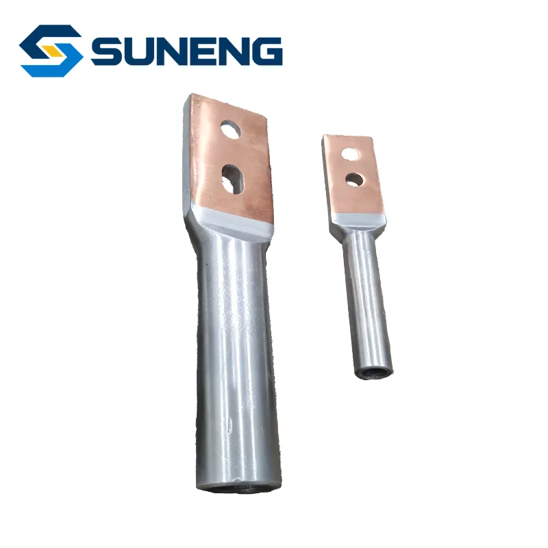
SYG-ZQ terminal product reference. This image does not show a failed connection or diagnose a heating problem.
First, make the observation comparable
Record when the heating occurs, the load at that time and the measurement method. A temperature reading without those details is difficult to compare with a previous inspection or another terminal. A thermal image can help locate an anomaly, but it does not prove its cause. Fluke’s electrical inspection guidance explains why load and connection condition matter when interpreting thermal patterns.
Ask the inspection team to retain the original image or readings, not only a cropped screenshot with the hottest number. Identify the terminal, surrounding equipment, ambient conditions and observation point. If operating conditions changed between inspections, mark that difference explicitly. Do not use an arbitrary temperature from an online article as a universal pass/fail threshold.
Review three interfaces, not one product label
Interface
Information to retrieve
Decision it supports
Conductor to barrel
Cable datasheet, conductor construction, terminal drawing, tool and die identification, crimping record.
Whether the selected conductor and approved compression system correspond.
Copper-aluminium transition
Exact model and batch, transition design, sample identification and applicable test records.
Whether the evidence covers the supplied transition, rather than a visually similar sample.
Palm to equipment
Mating material and finish, mounting drawing, hardware, assembly instructions and inspection history.
Whether the equipment interface was specified and assembled as intended.
Use the table to allocate questions, not to diagnose a failure from a photograph. For example, an improved copper-aluminium transition does not resolve an unsuitable conductor-to-barrel fit or an incorrect equipment connection. Keep those workstreams separate until the evidence links them.
What to check before buying a different terminal
Confirm the identity. Record the actual marking, supplier reference, drawing revision and delivered batch. A purchase-order description alone may omit the exact variant.
Reconstruct the installation. Ask for the approved instructions and the tools actually used. An installer remembering the tool tonnage is not the same as a complete tool-and-die reference.
List changes. Note any cable replacement, rerouting, enclosure change, increased loading, maintenance or water exposure since commissioning.
Define the missing evidence. Separate unknown dimensions from missing installation records and unresolved operating measurements.
Agree corrective action. Have the responsible engineer determine whether further inspection, testing, reassembly or replacement is appropriate before procurement finalises the replacement scope.
Do not cut strands, enlarge the barrel, re-drill the palm or add an unapproved sleeve merely to make a replacement fit. If the interface cannot be matched by a standard part, submit it for a documented custom design.
Copy this heating-enquiry checklist
Site and equipment reference; system duty and operating environment.
Terminal model, batch and drawing; conductor material, construction and nominal size.
Actual connection arrangement and photographs collected under safe site procedures.
Observed temperature pattern, measurement method, load, ambient conditions and time.
Tool, die and installation-instruction references; available assembly and inspection records.
When the issue began and what changed beforehand.
Required investigation documents, replacement quantity and shutdown window.
How to compare a proposed improvement
Ask the supplier to identify the offered sample and the comparison conditions. For resistance or temperature-rise evidence, request the conductor arrangement, measuring points, test method and operating or test conditions. A sample photograph or a percentage without that context cannot establish the benefit in your installation. Our test-report checklist explains how to review the supporting documents.
SUNENG can review standard and custom copper-aluminium connection requirements. Send the information above with your present interface so the discussion starts with compatibility and evidence, rather than a promise that changing the lug will automatically solve the issue. See our copper-aluminium terminal guide for the process video and specification checks.
A copper-aluminium terminal must match the conductor, equipment interface and installation method as well as the intended electrical duty. This guide combines SUNENG process and installation footage with the specification and evidence checks buyers need before approving a standard or custom connection.
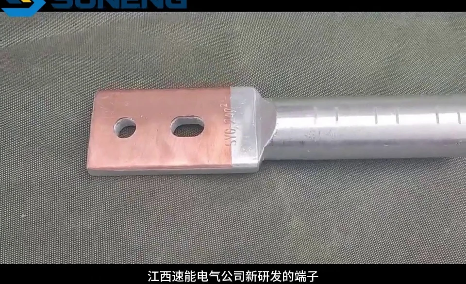
Transition geometry is reviewed before the terminal is installed.
Click play to load the YouTube player. If playback is unavailable, use the YouTube link.
Why copper-aluminium transitions need a controlled interface
Copper and aluminium have different electrochemical behaviour, surface characteristics and thermal response. When the interface is exposed to moisture, contamination or an unsuitable joining method, the connection can become harder to inspect and maintain. The video uses coastal and humid operating conditions to explain why the transition area deserves deliberate material selection, sealing and installation control.
The practical question is not simply whether copper can be connected to aluminium. It is whether the complete transition can be specified, prepared, compressed and protected in a way that is compatible with the conductor, the equipment terminal and the working environment.
What the process review video shows
The video introduces a SUNENG SYG-ZQ copper-aluminium terminal and compares samples made using the new metallurgical bonding route with a traditional joining sample. It then follows the preparation and installation sequence, including conductor stripping, hydraulic crimping and waterproof cold-shrink protection.
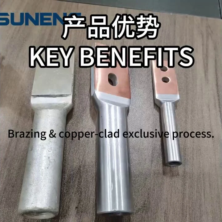
Same-model samples are compared to make the process difference visible.
Metallurgical bonding as the transition strategy
In the comparison section, the new terminal is presented as a copper-aluminium metallurgical bonding solution rather than a simple overlap of two dissimilar metals. The aim is to create a defined transition zone that can be inspected as part of the product and then connected to the conductor using the specified compression method.
This video is a process and product introduction. It shows the design intent and the installation route; it is not, by itself, a substitute for a product test report, type-test evidence or project-specific acceptance criteria. For a live specification, confirm the applicable conductor range, terminal dimensions, compression die, sealing method and supporting technical documents.
Installation workflow shown in the video
1. Confirm the terminal and conductor dimensions
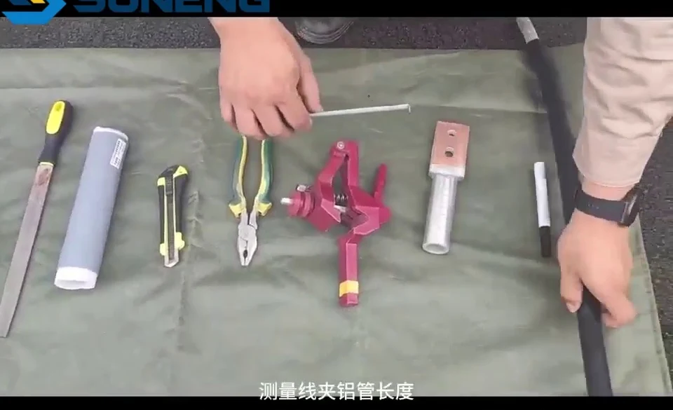
The operator first checks the aluminium tube length and the conductor preparation area. This establishes how far the conductor should enter the terminal and where the protective sleeve will sit after crimping.
Preparation starts with the terminal, conductor and installation tools in one view.
2. Prepare the conductor
The insulation is removed to the required length and the conductor surface is prepared without damaging the strands. The exact stripping length and any surface treatment should follow the selected terminal’s installation instruction.
3. Complete the hydraulic crimp
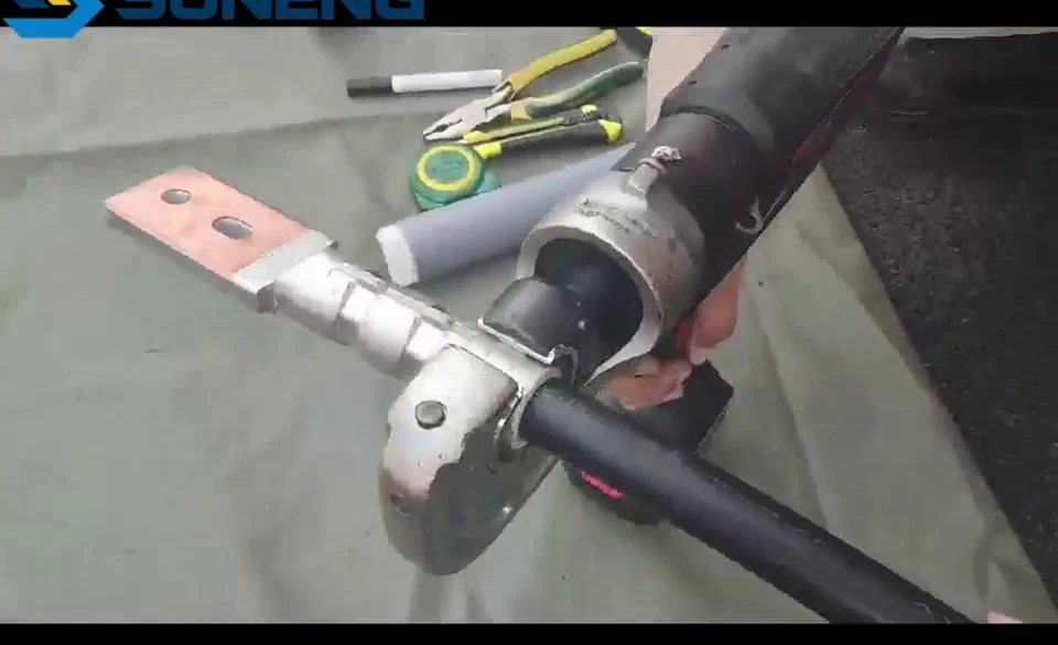
The terminal is positioned on the conductor and compressed with a hydraulic tool. The tool and die combination are part of the connection specification: using a different die sequence or an unverified tool can change the finished geometry and contact pressure.
Hydraulic compression creates the specified mechanical and electrical contact.
4. Add waterproof cold-shrink protection
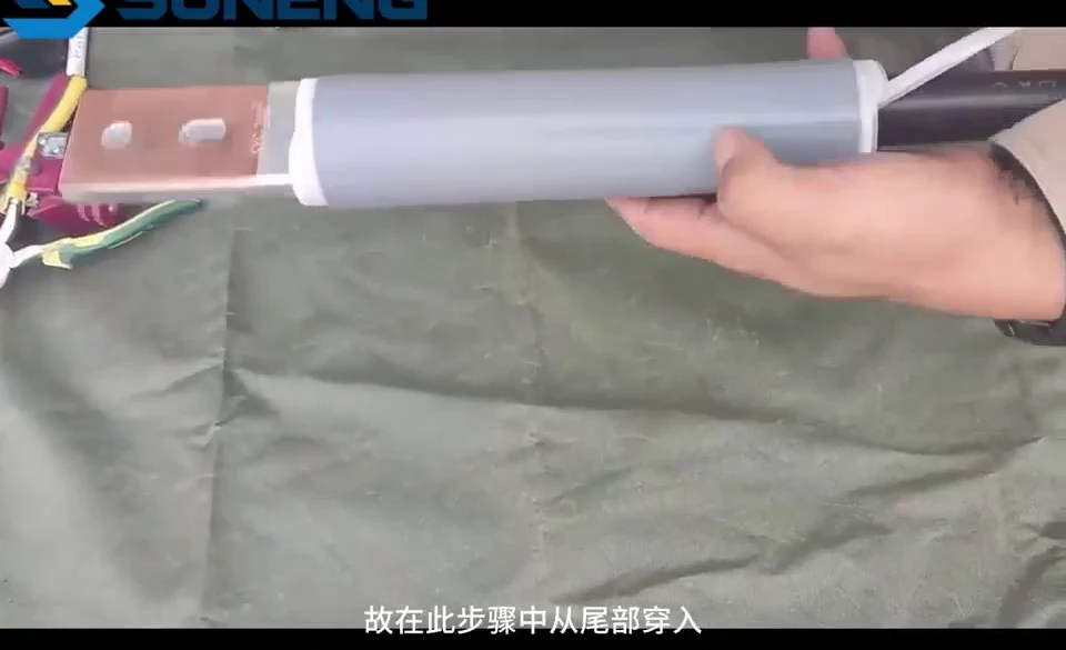
The video then shows the cold-shrink tube being positioned over the transition area. The sleeve helps shield the interface from water ingress and environmental contamination. It should be installed after the connection has been checked and in accordance with the selected product’s dimensions.
Finished connection and field application
The finished terminal combines the transition body, compressed conductor and protective sleeve.
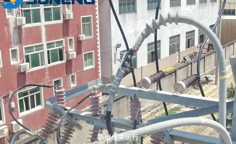
The final section shows the terminal installed on power equipment. That view is useful for checking the overall envelope, cable approach and clearance around the connection. It also highlights why the installation method needs to be considered together with the terminal design: the product, tool, conductor and protection system form one installation package.
Field application review includes routing, clearance and protection around the connection.
Separate the three interfaces when reviewing a terminal
Evaluate the conductor-to-barrel crimp, the copper-aluminium transition within the terminal, and the palm-to-equipment connection separately. Improving the transition process does not remove the need for the correct conductor, tooling and mounting arrangement. Ask the supplier to state the applicable conductor construction, barrel dimensions, palm material, hole pattern and approved installation method for the offered size.
Nominal cable cross-section is a starting point, not a complete dimensional specification. Supply the actual conductor diameter and construction, and check that the palm fits the equipment interface with the intended hardware and clearance. Any required angle or hole-pattern change should appear on the approved drawing.
What a resistance or temperature-rise comparison needs to show
Ask for the sample identities, conductor and connection arrangement, measurement positions, test method and the conditions for each comparison. For temperature-rise work, review the current, ambient temperature, sensor locations and the stated test endpoint. Compare results only when the test arrangements support a meaningful comparison.
The available SUNENG temperature-rise record carries the SYG designation; SYG-ZQ is the internal name used for the new series. Request a written cross-reference to the particular sample, size and drawing offered. A record for one sample should not be treated as proof of an identical percentage improvement across every size and installation.
Ask for the connector-specific tool and die reference, compression sequence, number of compressions and inspection requirements. The installation information from an established connector manufacturer illustrates why these details are tied to a specific connector system; its die numbers or dimensions must not be transferred to a SUNENG terminal. Confirm the required SUNENG instructions for the selected model.
For a sealing sleeve or cable accessory, confirm the dimensional range and intended function. A sleeve used for environmental protection is not automatically a complete medium-voltage termination system. Installation and testing must be carried out by qualified personnel under the applicable isolation and site procedures.
When the connection needs a custom design
SUNENG’s copper-aluminium metallurgical composite process supports batch production and can be reviewed for different copper-aluminium transition fittings. For a non-standard request, send the mating drawing or measured interface, conductor details, electrical and mechanical requirements, operating environment, and sample and production quantities. Agree a proposed drawing, prototype review and verification plan before releasing the production design.
Conductor material, cross-section, strand construction and insulation diameter.
Terminal model, interface dimensions and equipment-side connection requirements.
Approved hydraulic tool, die set, compression sequence and inspection method.
Cold-shrink or other sealing arrangement, including the environmental exposure.
Required drawings, product data, test records and project acceptance criteria.
For copper-aluminium transition work, a clear technical request is more useful than a product name alone. Send the conductor data, equipment interface, operating environment and required documents so the proposed terminal and process can be reviewed as a complete scope.
We use essential cookies for site security and optional analytics cookies to understand which pages are useful. Analytics stays off unless you allow it.
Privacy controls
Cookie preferences
Choose whether SUNENG may use anonymous analytics to improve this website. You can change this choice at any time.
Essential cookies
Required for security, forms and core website functions.
Always active
Advertising and personalization cookies are not enabled by this website.