Updated 13 October 2026
A copper-aluminium terminal must match the conductor, equipment interface and installation method as well as the intended electrical duty. This guide combines SUNENG process and installation footage with the specification and evidence checks buyers need before approving a standard or custom connection.
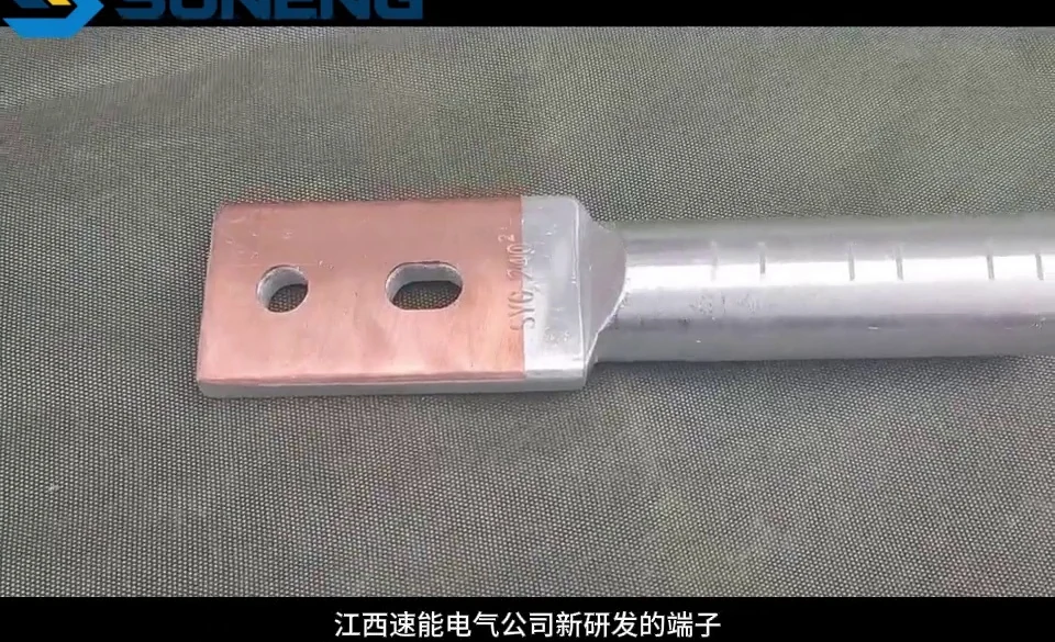
Watch SUNENG’s copper-aluminium terminal introduction

Click play to load the YouTube player. If playback is unavailable, use the YouTube link.
Why copper-aluminium transitions need a controlled interface
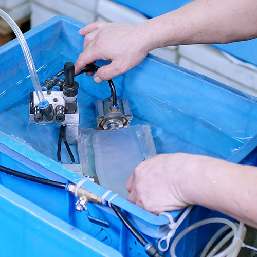
Copper and aluminium have different electrochemical behaviour, surface characteristics and thermal response. When the interface is exposed to moisture, contamination or an unsuitable joining method, the connection can become harder to inspect and maintain. The video uses coastal and humid operating conditions to explain why the transition area deserves deliberate material selection, sealing and installation control.
The practical question is not simply whether copper can be connected to aluminium. It is whether the complete transition can be specified, prepared, compressed and protected in a way that is compatible with the conductor, the equipment terminal and the working environment.
What the process review video shows
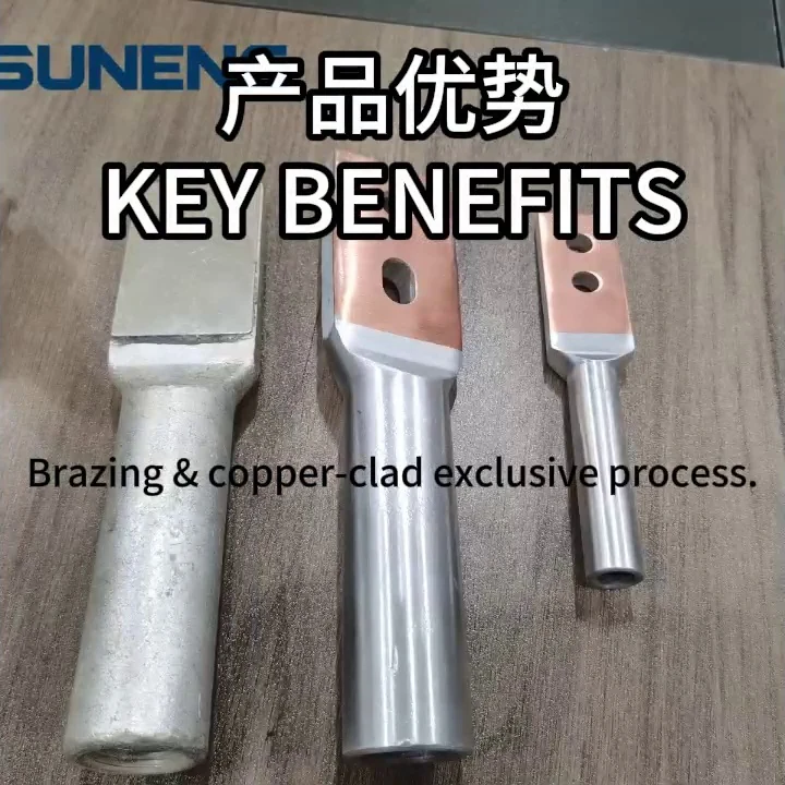
The video introduces a SUNENG SYG-ZQ copper-aluminium terminal and compares samples made using the new metallurgical bonding route with a traditional joining sample. It then follows the preparation and installation sequence, including conductor stripping, hydraulic crimping and waterproof cold-shrink protection.
Metallurgical bonding as the transition strategy
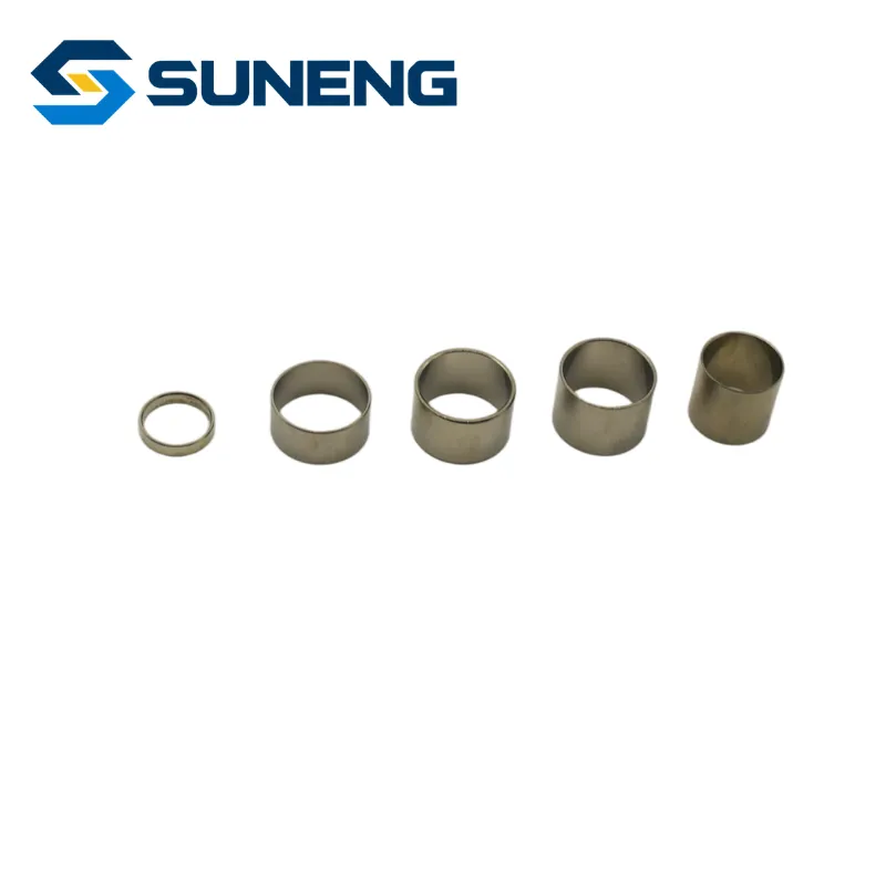
In the comparison section, the new terminal is presented as a copper-aluminium metallurgical bonding solution rather than a simple overlap of two dissimilar metals. The aim is to create a defined transition zone that can be inspected as part of the product and then connected to the conductor using the specified compression method.
This video is a process and product introduction. It shows the design intent and the installation route; it is not, by itself, a substitute for a product test report, type-test evidence or project-specific acceptance criteria. For a live specification, confirm the applicable conductor range, terminal dimensions, compression die, sealing method and supporting technical documents.
Installation workflow shown in the video
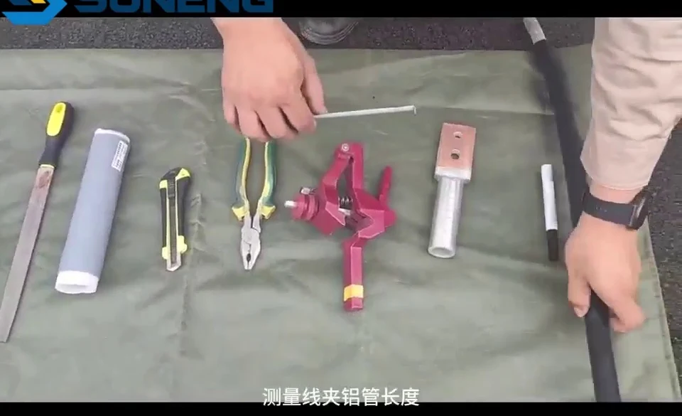
1. Confirm the terminal and conductor dimensions
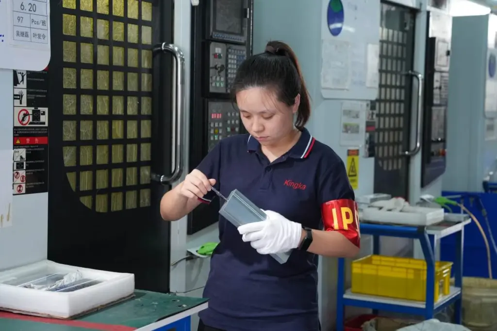
The operator first checks the aluminium tube length and the conductor preparation area. This establishes how far the conductor should enter the terminal and where the protective sleeve will sit after crimping.
2. Prepare the conductor
The insulation is removed to the required length and the conductor surface is prepared without damaging the strands. The exact stripping length and any surface treatment should follow the selected terminal’s installation instruction.
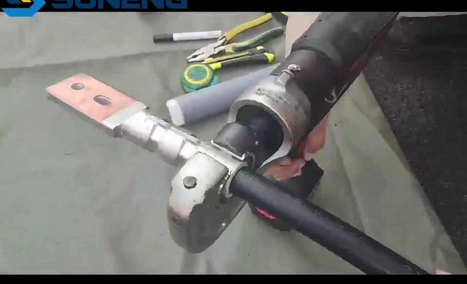
3. Complete the hydraulic crimp
The terminal is positioned on the conductor and compressed with a hydraulic tool. The tool and die combination are part of the connection specification: using a different die sequence or an unverified tool can change the finished geometry and contact pressure.
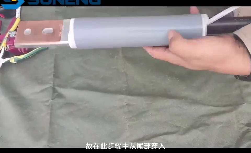
4. Add waterproof cold-shrink protection
The video then shows the cold-shrink tube being positioned over the transition area. The sleeve helps shield the interface from water ingress and environmental contamination. It should be installed after the connection has been checked and in accordance with the selected product’s dimensions.
Finished connection and field application
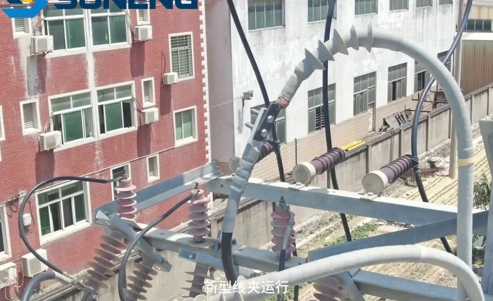
The final section shows the terminal installed on power equipment. That view is useful for checking the overall envelope, cable approach and clearance around the connection. It also highlights why the installation method needs to be considered together with the terminal design: the product, tool, conductor and protection system form one installation package.
Separate the three interfaces when reviewing a terminal
Evaluate the conductor-to-barrel crimp, the copper-aluminium transition within the terminal, and the palm-to-equipment connection separately. Improving the transition process does not remove the need for the correct conductor, tooling and mounting arrangement. Ask the supplier to state the applicable conductor construction, barrel dimensions, palm material, hole pattern and approved installation method for the offered size.
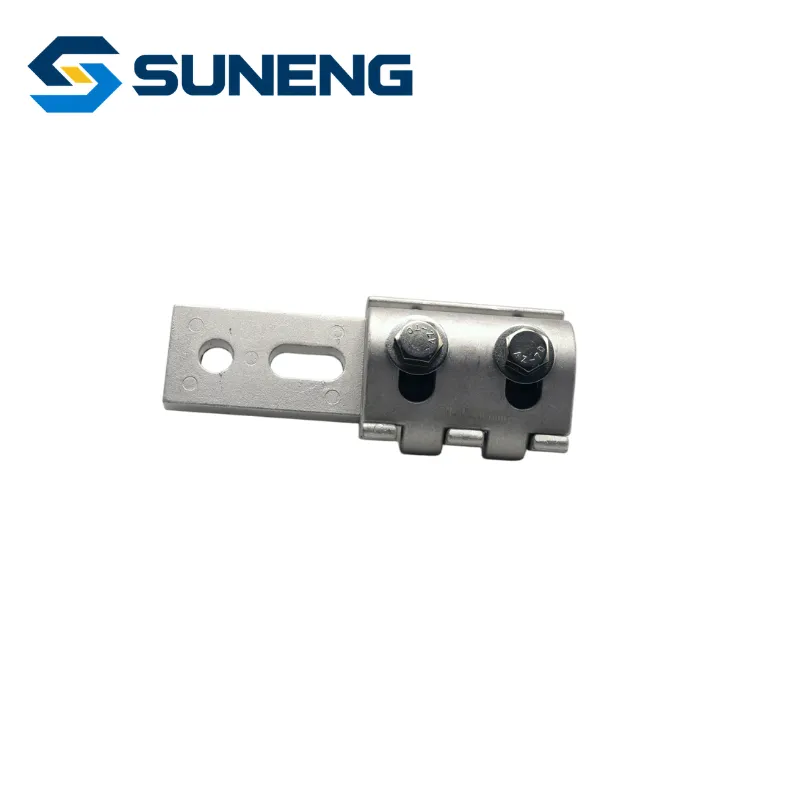
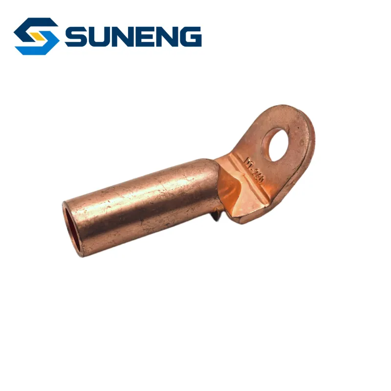
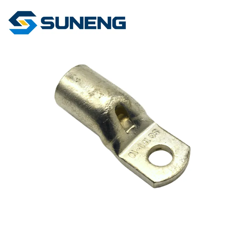
Nominal cable cross-section is a starting point, not a complete dimensional specification. Supply the actual conductor diameter and construction, and check that the palm fits the equipment interface with the intended hardware and clearance. Any required angle or hole-pattern change should appear on the approved drawing.
What a resistance or temperature-rise comparison needs to show
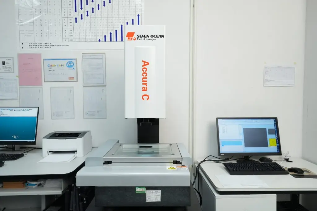
Ask for the sample identities, conductor and connection arrangement, measurement positions, test method and the conditions for each comparison. For temperature-rise work, review the current, ambient temperature, sensor locations and the stated test endpoint. Compare results only when the test arrangements support a meaningful comparison.
The available SUNENG temperature-rise record carries the SYG designation; SYG-ZQ is the internal name used for the new series. Request a written cross-reference to the particular sample, size and drawing offered. A record for one sample should not be treated as proof of an identical percentage improvement across every size and installation.
Watch the process video to understand the product and installation concept, then use the relevant drawings and test records for acceptance decisions. See SUNENG’s available certificates and test records and the document-review checklist.
Specify the tooling and sealing with the terminal
Ask for the connector-specific tool and die reference, compression sequence, number of compressions and inspection requirements. The installation information from an established connector manufacturer illustrates why these details are tied to a specific connector system; its die numbers or dimensions must not be transferred to a SUNENG terminal. Confirm the required SUNENG instructions for the selected model.
For a sealing sleeve or cable accessory, confirm the dimensional range and intended function. A sleeve used for environmental protection is not automatically a complete medium-voltage termination system. Installation and testing must be carried out by qualified personnel under the applicable isolation and site procedures.
When the connection needs a custom design
SUNENG’s copper-aluminium metallurgical composite process supports batch production and can be reviewed for different copper-aluminium transition fittings. For a non-standard request, send the mating drawing or measured interface, conductor details, electrical and mechanical requirements, operating environment, and sample and production quantities. Agree a proposed drawing, prototype review and verification plan before releasing the production design.
Explore copper-aluminium terminals and custom development, or send your connection requirement.
Installation reference
BURNDY: Aluminium compression-terminal installation training illustrates connector, conductor and tooling matching. It is not an installation instruction or certification for SUNENG products.
What to confirm before specifying
- Conductor material, cross-section, strand construction and insulation diameter.
- Terminal model, interface dimensions and equipment-side connection requirements.
- Approved hydraulic tool, die set, compression sequence and inspection method.
- Cold-shrink or other sealing arrangement, including the environmental exposure.
- Required drawings, product data, test records and project acceptance criteria.
For copper-aluminium transition work, a clear technical request is more useful than a product name alone. Send the conductor data, equipment interface, operating environment and required documents so the proposed terminal and process can be reviewed as a complete scope.
Review the copper-aluminium process Discuss a project requirement