Updated 16 October 2026
A cold plate for an IGBT, inverter or other power-electronics assembly is defined by the heat-source map and mounting interface as much as by its external dimensions. A useful specification connects the semiconductor layout, coolant circuit and inspection plan before the channel design is released.
Start with the heat-source map
Identify each heat source, its footprint, expected load and duty cycle. Record the maximum permitted component temperature and the temperature available at the coolant inlet. The plate should place effective cooling under the real heat sources while preserving the mounting and service features of the assembly.
- Component locations and contact footprints
- Continuous and peak heat load
- Temperature limits and ambient conditions
- Mounting holes, fasteners and interface material
- Clearances for busbars, sensors and covers
Describe the coolant conditions, not only the flow rate
State the coolant composition, inlet temperature range, available flow, pressure budget and connection arrangement. Flow rate alone does not establish cooling performance. Channel length, cross-section, distribution, heat-source position and the rest of the circuit affect both heat transfer and pressure drop.
Make the contact interface part of the drawing review
Flatness, surface finish, hole position and mounting pressure influence thermal contact. Define the critical contact areas and the dimensions that cannot change. If a thermal interface material is used, identify its thickness or installation condition where that information is part of the acceptance requirement.
Choose the construction after the requirements are clear
Embedded tube, brazed, machined-channel and friction-stir-welded routes solve different combinations of geometry, sealing, flow and production requirements. The correct route is project-specific. See the FSW liquid cold plate example and the thermal manufacturing page for a starting point.
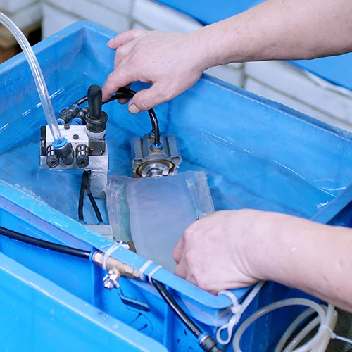
Define sample acceptance before production
Agree the drawing revision, critical dimensions, pressure or leak method, flow conditions, cleanliness requirements and thermal validation responsibility. Include the quantity and documentation required with delivery. For a project review, use the OEM/ODM route or send your power-electronics requirements.