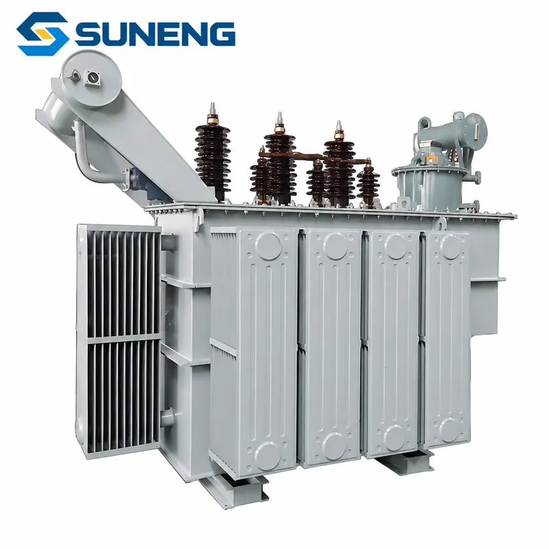
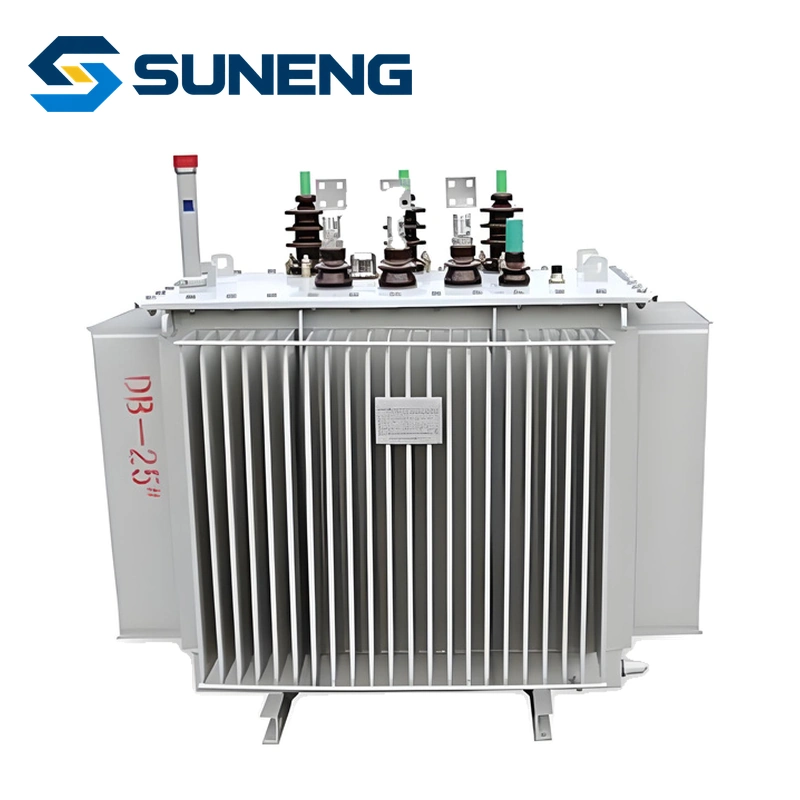
Adding up the chargers’ advertised kilowatts is not enough to explain how a charging hub will load its transformer. The missing information is the AC-side demand over time, the charging controls and the electrical conditions at the transformer itself.
This matters when a site expands in stages. A lightly used location may appear comfortable during its first months, then operate very differently once fleet utilization, concurrent sessions or charging policy changes. Design around the intended duty, not the quietest period in the site’s history.
Separate vehicle output from grid input
A charger’s DC delivery rating and its upstream AC demand are not the same measurement. Conversion losses and auxiliaries contribute to input power. Reactive power and waveform distortion also affect RMS current and apparent power. Evaluate the defined metering point and use the charger’s AC input data rather than treating a DC marketing figure as a transformer loading calculation.
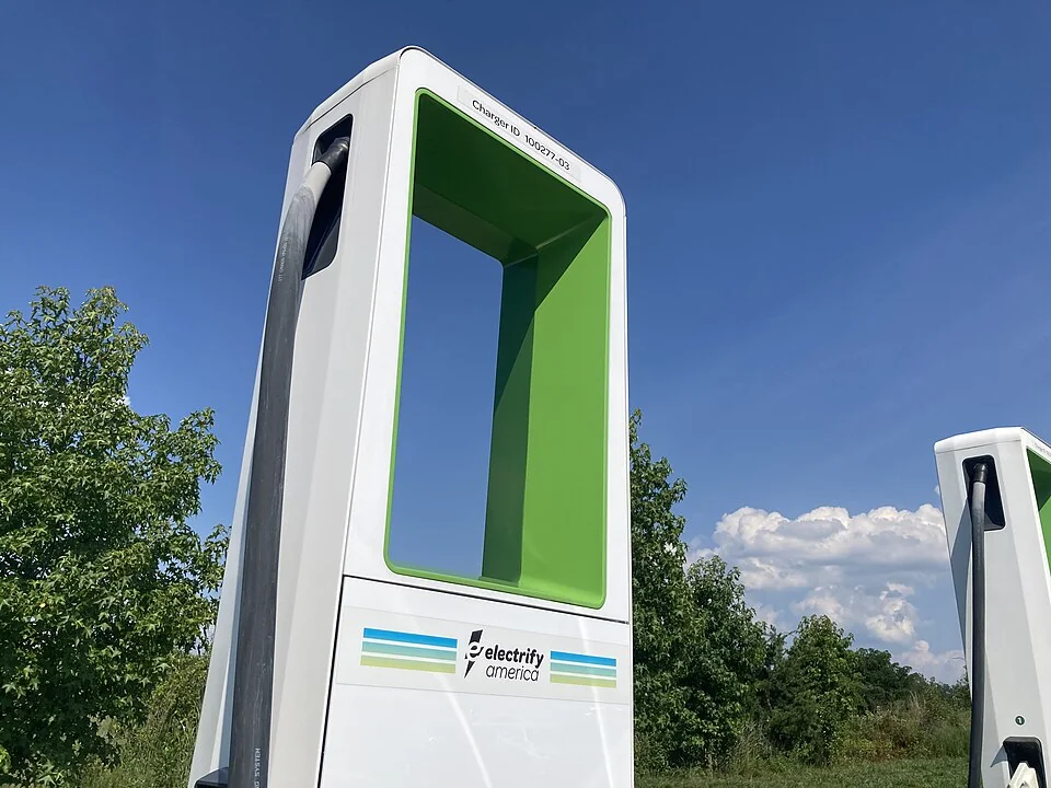
Demand controls complicate this further. Six chargers capable of high individual output do not necessarily operate at their maximum simultaneously. Equally, a controller’s configured site cap is not useful evidence unless the operating arrangement, metering location and failure behavior are understood.
Schneider Electric explains that harmonics can contribute to transformer overloading and excessive heating.[1] That is a reason to obtain relevant data, not a reason to label every modern fast charger a severe harmonic load. Input-stage design and operating point matter. Measurements from a different charger generation are not an adequate substitute.
Read a time series, not just one maximum
Consider two hypothetical sites with the same 1 MVA nameplate transformer. One has brief demand peaks and long recovery periods. The other sustains a similar peak for much of a shift. Their thermal histories need not be equivalent, even if their recorded maximum demand is identical.
Charging demand and local grid capacity also interact. The US Department of Energy’s Alternative Fuels Data Center recommends coordinating near- and long-term charging requirements with the utility and considering future expansion.[2] For a project assessment, convert that planning requirement into a measured or modeled daily and seasonal profile.
Include operating cases that are easy to forget:
- A fleet returns on schedule with several depleted vehicles.
- Additional dispensers are added without increasing the site’s import limit.
- A hot day raises both ambient temperature and enclosure conditions.
- Charging is concentrated into a shorter tariff window.
- Communications or supervisory controls are unavailable.
Do not assume that a demand-management arrangement satisfies a protection or capacity requirement merely because it works during a normal demonstration. The responsible designer needs to decide which control functions may be relied upon and under which constraints.
Use harmonic data with its operating context
A single percentage labeled “THD” is incomplete. Ask whether it is current or voltage distortion, the measurement location, load level, harmonic spectrum and measurement method. A current-distortion percentage can appear high at light load while the actual harmonic amperes remain small. Conversely, a modest percentage at high fundamental current can represent a larger absolute harmonic burden.
Harmonics are only one possible explanation for heating. Supply voltage, unbalance, cooling restrictions, terminal condition and the actual duty can change the outcome. A transformer should not be described as “harmonic-ready” solely because a sales sheet includes a familiar term or rating.
For an application review, use the transformer manufacturer’s loss and thermal guidance with the expected current spectrum and operating profile. Do not infer a universal derating percentage from charger count. A numerical derating decision without the design basis can be either wasteful or unsafe.
Build a measurement plan that separates the causes
| Evidence | Decision it supports | Common misinterpretation |
|---|---|---|
| Time-aligned AC demand and charging-controller logs | Whether session behavior matches the assumed duty | A quiet week’s maximum represents the mature site |
| RMS current, voltage, unbalance and harmonic spectrum | Whether electrical conditions differ from the design inputs | One THD value describes every operating point |
| Ambient and available transformer thermal indicators | Whether heat tracks duty, weather or cooling changes | Surface temperature directly equals internal winding hotspot |
| Connection inspection and comparable thermal images | Whether heating is localized at an interface | Every hot connection means the transformer is undersized |
| Control configuration and expansion record | Whether site changes have consumed the original margin | The original design remains valid after new chargers are added |
Arrange measurements through qualified personnel using the site’s safety and operating procedures. The table is a scoping tool, not instructions for opening live equipment or installing instruments.
Make expansion a design checkpoint
Before a new charging phase goes live, reconcile the installed equipment against the original assumptions. Record the new AC demand envelope, expected utilization, changes in power-quality behavior and how demand management will operate. If the study supports a different transformer arrangement, document the reason rather than merely increasing nameplate kVA as a precaution.
SUNENG can discuss transformer and project supply requirements with your electrical design team. Our site-condition transformer article addresses another boundary that charging projects should not ignore: equipment performance depends on its installation environment as well as its nominal rating.
The question to ask before the next expansion: what will the transformer experience during the busiest intended operating period—not what is the sum of the numbers printed on the dispensers?
Source notes
[1] Schneider Electric, Karl Kaiser, 5 Harmonic Mitigation Methods That Help Keep Costs Down and Production Running, February 21, 2017. [2] US Department of Energy, Alternative Fuels Data Center, Procurement and Installation for Electric Vehicle Charging Infrastructure, accessed November 5, 2026. Sources support the general effects of harmonics and infrastructure planning. The operating scenarios and evidence table are original editorial analysis; no universal transformer sizing or derating rule is asserted.