A bright spot in a thermal image is a reason to investigate—not a diagnosis by itself. Before calling a terminal defective, ask whether the image reflects a changed electrical condition, a different surface or a reflected heat source.
Thermography is attractive because it can reveal temperature patterns without making contact with every component. Its weakness is equally important: a camera receives infrared radiation, not a direct reading of contact resistance or internal winding temperature. The engineering value comes from combining the image with operating context.
Three traps that change the story
1. Comparing unequal electrical loads
Two phases, two cabinets or two inspections on different days may not carry the same load. A visually warmer path can be the more heavily loaded path rather than the defective one. A low-load inspection can also fail to expose behavior that appears during the equipment’s demanding duty.
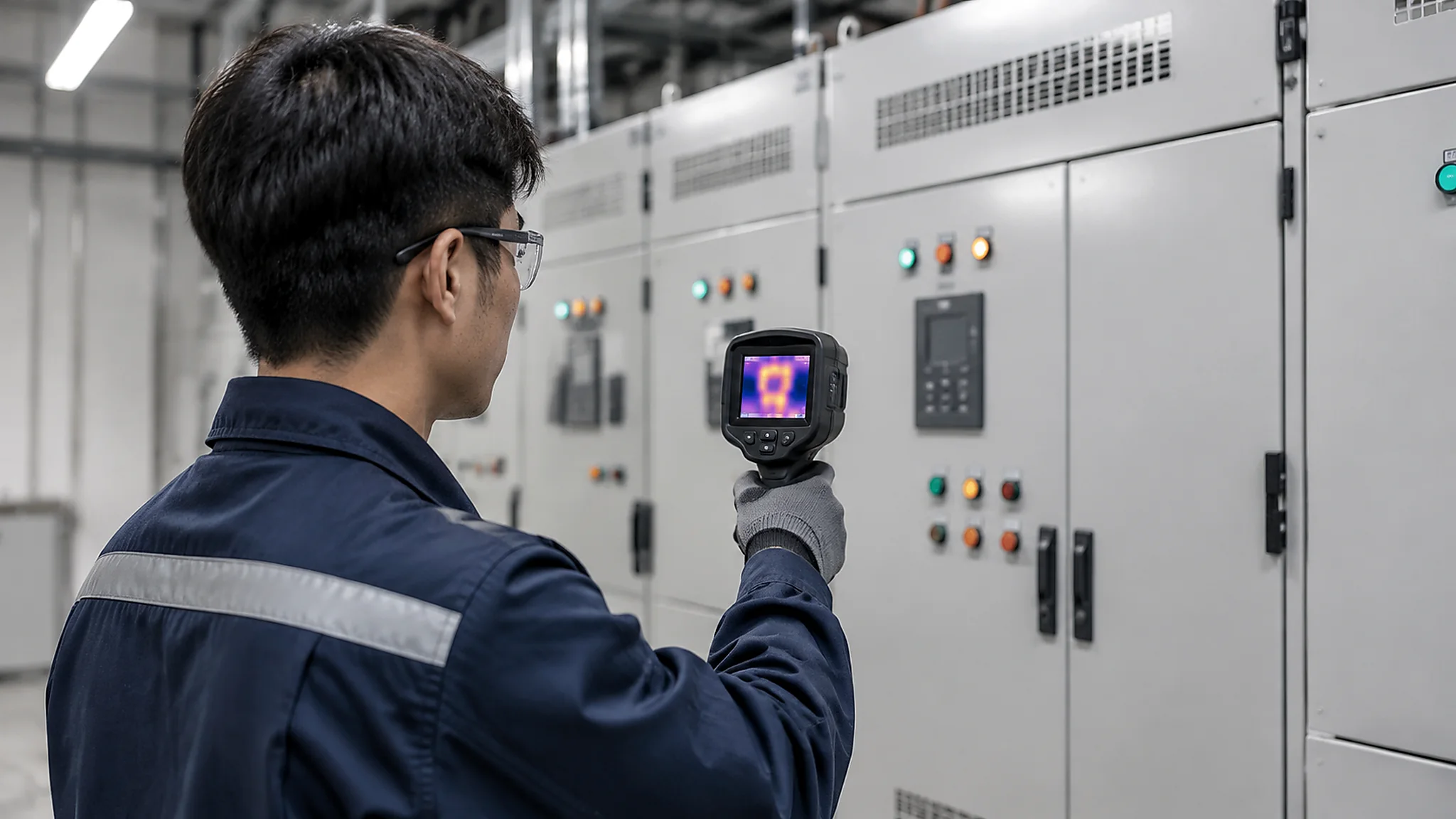
FLIR’s electrical-inspection guidance emphasizes the relationship between observed heating, equipment condition and the load during inspection.[1] The practical lesson is to save the load context with the image, not to take a screen capture and discard the operating record.
2. Trusting shiny metal as though it were a uniform surface
Bare reflective metal, painted surfaces and insulated parts do not present the same radiative behavior. Surface emissivity, reflected apparent temperature, viewing position and intervening materials can change what the camera reports. FLIR’s measurement guidance explains why those parameters affect temperature interpretation.[2]
This is especially relevant when comparing a plated terminal with an adjacent painted enclosure. Their displayed colors do not automatically establish an equivalent comparison of actual surface temperatures. A reflection that moves when the viewing position changes is a clue, but it is not a substitute for a competent measurement method.
3. Letting the palette manufacture a dramatic fault
An automatically scaled image can make a small temperature difference look severe. Two pictures with different scale ranges cannot be compared reliably by color alone. Preserve radiometric data when available, scale information and a matching visible-light view. The screenshot in a messaging app may lose the information needed for the next engineering decision.
A useful field record contains more than a temperature
The following record structure is intended for qualified inspection personnel working under the site’s safe procedures. It does not authorize opening energized enclosures or approaching live parts. Some observation methods may require planned isolation or approved inspection windows.
| Record field | What it helps establish |
|---|---|
| Asset and exact connection identity | Whether a later image shows the same physical joint |
| Date, operating state and electrical load | Whether observations are comparable |
| Ambient conditions and relevant local heat sources | Whether surrounding conditions changed |
| Visible-light image and camera position | Whether geometry, reflections or obstruction explain the pattern |
| Camera, lens, settings and measurement method | Whether a numerical comparison is defensible |
| Peer connections and historical baseline | Whether the behavior is local or common to the assembly |
| Action owner and follow-up condition | Whether the observation leads to a controlled decision |
If information is missing, record that limitation. Guessing an emissivity value after the fact does not reconstruct the original measurement conditions.
Use the pattern to choose the next question
Imagine three comparable outgoing connections on an assembly. One looks warmer in the initial image. First check whether the electrical loads are comparable. Then check whether the surfaces and viewing conditions permit a meaningful thermal comparison. If those checks support a genuine localized difference, review the trend and the joint’s installation history before deciding on the next action.
Contrast that with a whole enclosure appearing warmer during a higher-load period. That pattern may lead toward ventilation, duty or surrounding conditions rather than one defective connection. These are diagnostic branches, not a claim that any image alone excludes another fault.
Our copper–aluminium terminal heating article follows the physical-connection questions once a credible issue has been identified. This article concerns the earlier step: making sure the thermal observation supports that investigation.
Avoid a universal temperature threshold
A surface temperature acceptable for one assembly may be inappropriate for another material, insulation system, duty or operating environment. Risk also depends on the consequence of failure, progression and the availability of safe corrective action. An isolated value cannot establish all of that.
Use the applicable equipment limits, the site’s inspection criteria and a competent assessment to determine the response. This may call for planned investigation or urgent action, but the decision should not be invented from a color palette. Nor should a normal-looking surface image be described as proof that every internal connection is sound.
When work is required, preserve the initial evidence, follow the approved isolation and maintenance procedure, then verify the outcome under appropriately comparable operating conditions. Do not recommend live tightening as a shortcut. A thermal survey should improve maintenance decisions, not create a new exposure to electrical hazards.
Turn repeat inspections into useful history
For recurring surveys, agree asset names, viewpoints and the operating information to capture. The resulting series is more informative than a folder of unrelated “hot” pictures. It allows the engineering team to distinguish a worsening local pattern from a different load, a hotter day or a changed camera setup.
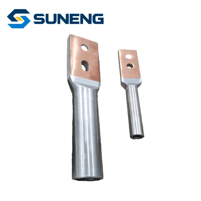
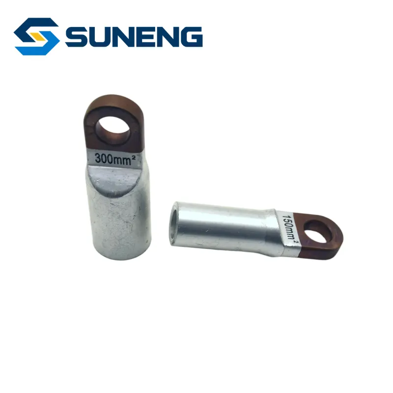
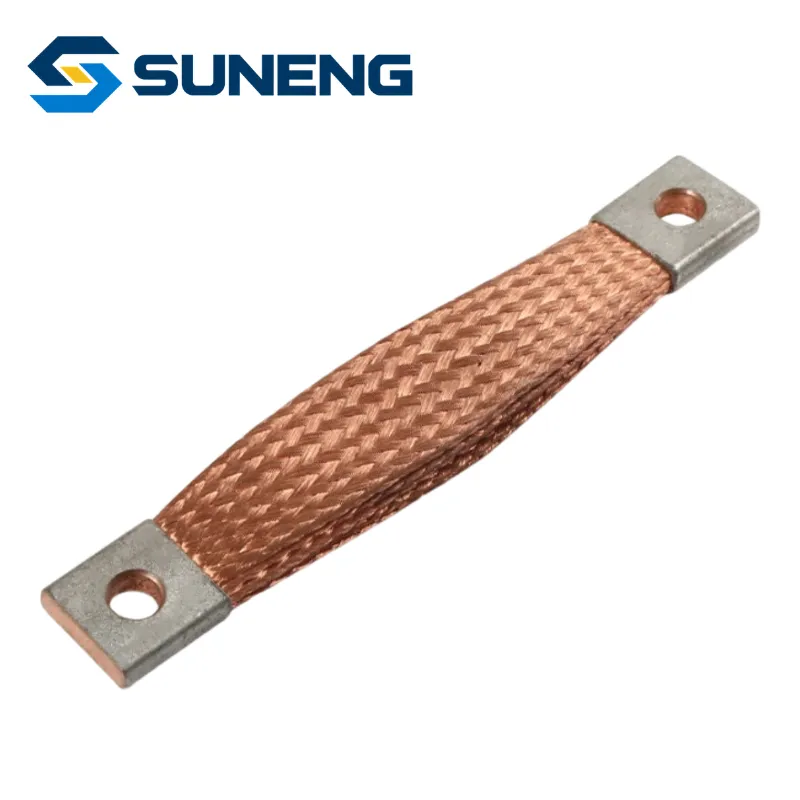
SUNENG can discuss connection components and supporting documentation when an assessment identifies a replacement or redesign need. For any replacement, keep the actual conductor, terminal interface, installation process and verification requirements attached to the request. A thermal image alone is not a complete replacement specification.
The useful outcome of thermography is a justified action—not the most dramatic image.
Source notes
[1] FLIR, John Keane, Top 5 Sidekicks Any Infrared-Inspecting Superhero Should Never Be Without. [2] FLIR, Infrared Camera Accuracy and Uncertainty in Plain Language. Referenced for recording load/environmental context and for infrared-measurement uncertainty. The record template and diagnostic sequence above are original editorial analysis; no fabricated thermogram or universal fault threshold is supplied.