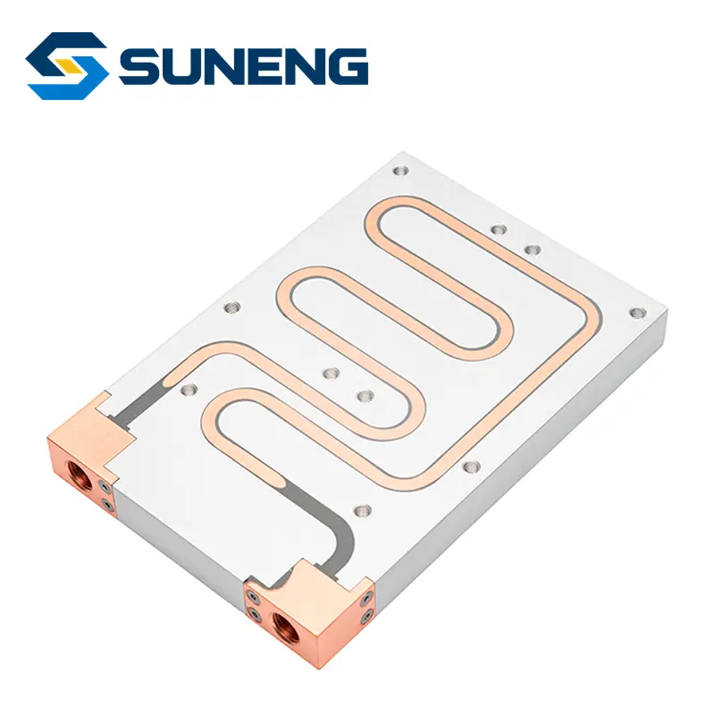
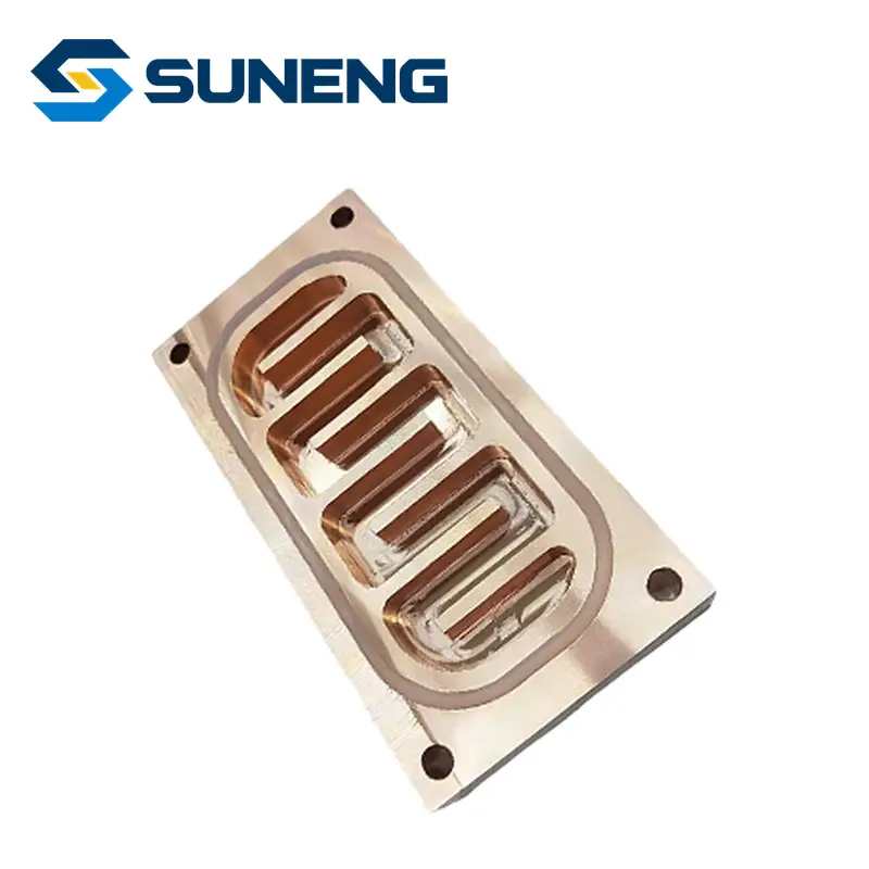
A cold plate can pass its factory leak test and still lose cooling capacity months after installation. The missing variable is often the loop around it: fluid chemistry, contamination and the way flow is distributed.
The move toward direct-to-chip cooling for dense AI computing makes this an operations problem, not simply a component-selection problem. A cold plate is one part of a circuit that also includes manifolds, hoses, quick-disconnects, filters, pumps and a coolant distribution unit. A useful investigation therefore starts with the complete wetted system, rather than asking immediately for a larger plate.
This article concerns water-based, single-phase technology cooling loops. It does not cover immersion cooling or two-phase refrigerant systems. The diagnostic examples are engineering illustrations, not results from a SUNENG installation.

A rising chip temperature does not identify the fault
Suppose a server’s monitored processor temperature rises while the coolant supply setpoint remains unchanged. That observation alone does not show whether the problem is inside the plate. Compare the operating condition with its commissioning baseline: actual device power, inlet temperature, branch flow and pressure drop, mounting condition, and the workload’s time history.
Use a small set of discriminating observations before replacing hardware:
| Observation under comparable load | Working hypothesis | Useful next evidence |
|---|---|---|
| One branch loses flow and its hydraulic resistance increases | Local restriction, trapped gas or a valve/connector problem | Branch flow and differential pressure, connector status and filter findings |
| Many devices warm together as supply temperature rises | Loop-level heat rejection or control issue | CDU trend, supply/return temperatures and operating state |
| One device warms while measured branch flow remains stable | Thermal interface, mounting, workload or local internal distribution issue | Mounting record, interface condition and device-power history |
| Readings jump after sensor replacement | Measurement or data-mapping problem | Sensor identity, calibration and channel assignment |
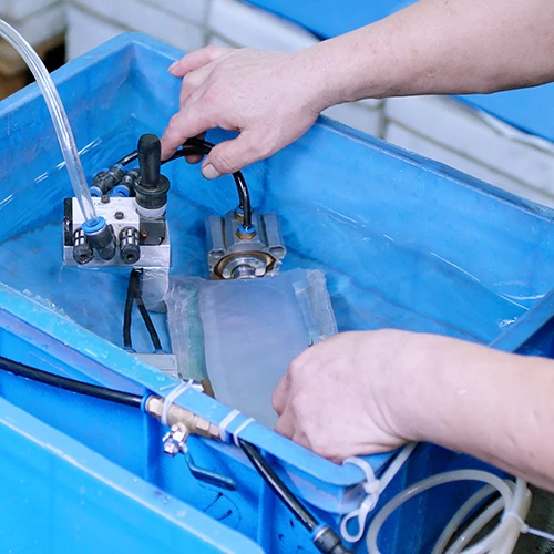
These are hypotheses, not diagnoses. In particular, compare pressure drop at the same flow and fluid condition; a lower measured differential pressure during falling flow does not prove the plate is clear.
Start with a fluid-and-materials register
Open Compute Project guidance treats water-based fluid use as a system-level issue involving water quality, materials and operating practice.[1] For an actual project, turn that principle into a register listing every wetted material and the fluid supplier’s compatibility conditions. Include less obvious items such as seals, brazing alloys, plating, hose liners and connector internals.
Do not infer compatibility from the cold plate’s outer body. An aluminium-looking assembly might contain another metal internally. Equally, do not transfer a coolant limit from one proprietary formulation to another: inhibited glycol blends and treated-water systems can have different approved monitoring ranges.
The practical questions are specific: What fluid was first filled? What concentration is now present? Was the make-up fluid the same formulation? Who approved the combination? Which lab or supplier method is used for checking it? Mixing two individually acceptable fluids is not automatically an acceptable maintenance practice.
Capture a baseline that can explain the next alarm
Before service, record an agreed operating point with the loop in a documented, stable condition. Include flow, pressure, inlet/outlet temperatures, fluid identity, filter status, valve positions and the equipment load. Record instrument accuracy and sensor locations as well. A trend without a consistent measurement location can become misleading after maintenance.
For perspective, the bulk heat balance is Q = ṁ × cp × ΔT. In a simplified water-only example, 1 litre/minute is approximately 0.0167 kg/s. With cp approximated as 4,180 J/(kg·K), a 5 K rise represents about 349 W of heat carried by that stream. This is a worked illustration, not a cold-plate rating; a glycol mixture, different temperature, sensor error or an unaccounted parallel branch changes the calculation. The balance also says nothing by itself about the hottest junction temperature.
This distinction is useful during fault finding. An apparently reasonable return temperature is not evidence that every parallel branch receives adequate flow.
Plan cleanliness around assembly and servicing
The contamination question is not just whether a supplier flushed a new plate. Debris can enter from pipework, a changed hose, an opened connector or a repair elsewhere in the loop. Define the cleanliness handover, protected storage, flushing method and sampling points before commissioning.
The filter should be selected with the complete circuit designer, including the smallest passages and the allowed pressure-drop budget. “Finer is always better” is not a complete answer: capture performance, bypass behavior, loading capacity and service access all matter. Avoid publishing a universal micron recommendation without the specific equipment requirements.
After a service intervention, make the restart evidence traceable to the changed branch. A sample from the wrong side of a filter cannot answer the same question as a sample taken at a return manifold. Preserve the location and method with the result.
Decide what warrants a shutdown with the system owner
An article cannot safely supply a universal alarm temperature, conductivity limit or flushing chemical for all AI racks. Instead, the commissioning plan should identify the equipment manufacturer’s operating envelope, approved fluid checks, leak-response procedure and escalation owner. Those become actionable rules because they refer to the actual system.
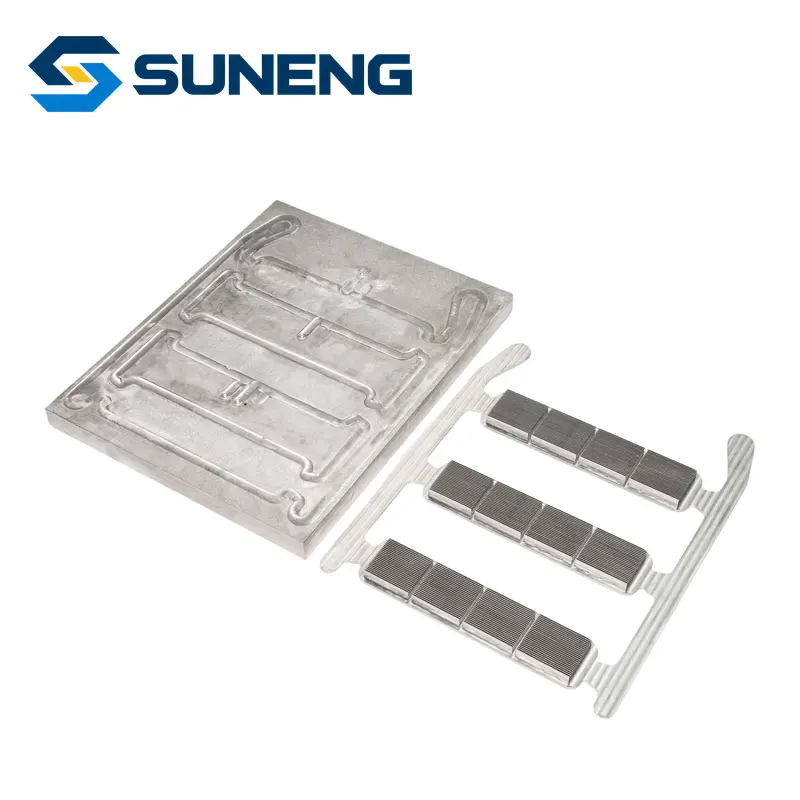
For new thermal components, the useful handover is therefore more than a drawing and a leak-test statement: include the documented flow path, wetted materials, approved operating envelope and the applicable verification record. Our cold-plate specification guide explains component-level inputs; this article adds the operational boundary around them.
The decision to make now: assign one owner to the loop’s compatibility and cleanliness record before assigning separate component purchase orders. SUNENG can discuss custom heat sinks and liquid cold plates against your defined interface and verification requirements; rack-level performance must still be assessed for the actual assembled cooling system.
Source notes
[1] Open Compute Project, Guidelines for Using Water-Based Transfer Fluids in Single-Phase Cold Plate-Based Liquid-Cooled Racks; used for the system-level scope of fluid quality and materials compatibility. The baseline worksheet, diagnostic table and numerical illustration above are original editorial analysis, not prescribed OCP acceptance limits.