A replacement switchgear device must perform the duty required by the circuit and work with the panel’s mechanism, controls and interlocks. Matching the voltage, current and mounting holes is only the start. Before requesting a substitute, identify whether the component is a circuit breaker, a load-break switch, a switch-fuse combination or a disconnector.
Send a single-line diagram and the existing device reference with the enquiry. Include the panel manufacturer and model if available. The equipment design establishes which switching, protection and isolation functions the device must provide.
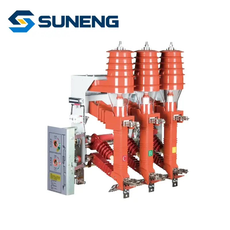
Start with the function in the circuit
| Device | Function to establish | Key replacement question |
|---|---|---|
| Circuit breaker | Switching normal current and interrupting specified fault current within its ratings. | Do interrupting duty, operating sequence and protection/control interfaces match? |
| Load-break switch | Switching the load duties for which it is rated. | Which making and breaking duties are specified, and how is fault protection provided? |
| Switch-fuse combination | Coordinated switching and fuse protection in the defined assembly. | Are the fuse selection, striker/trip arrangement and combination ratings confirmed? |
| Disconnector | Providing the specified isolation function, with any switching duty limited to its declared capability. | Does the operating scheme prevent use beyond that switching capability? |
A load-break switch with a making rating is not automatically a circuit breaker capable of interrupting the same fault current. Similarly, a vacuum interrupter in a device does not by itself identify the complete device’s function. Read the ratings and assembly description together.
Write the ratings with their meaning attached
Record rated voltage, insulation requirements, normal current and the relevant making, breaking or short-time withstand duties separately. Preserve the specified durations and operating sequences. A quotation that contains an unexplained current value in kA leaves too much open for a replacement decision.
Ask for the standard and edition applicable to the particular device and assembly, where specified by the project. The relevant IEC 62271 requirements differ between device types. A test record for a standalone component does not by itself establish the performance of a modified complete panel.
Check the control circuit before the order
Provide the control schematic and identify AC or DC supply voltage for each function. Record the closing and trip releases, charging motor, auxiliary contacts, position indication and connector pinout. Include any undervoltage release or other option fitted to the existing device.
- Which signals command closing and tripping, and which signals confirm position?
- Which contacts are required by the protection, remote-control and indication circuits?
- Which mechanical and electrical interlocks control operation?
- Which connectors, terminal numbers and cable lengths must match the existing panel?
Mark each answer on a comparison drawing. Describing both devices as “motor-operated” does not establish that their power supplies, wiring or control logic correspond.
Check the complete installation envelope
Measure mounting centres, phase spacing, terminal locations and operating-shaft position. Include mechanism travel, service access and the clearances required by the approved panel design. A photo from the front can conceal a different shaft location or terminal depth.
For a withdrawable device, include the truck, racking, contact and position-interlock interfaces. For fixed equipment, identify all mating conductors and supports. Ask the panel designer to review any change affecting clearances, barriers, protection or interlocking before accepting a substitute.
Define a clear purchase and approval boundary
State whether you require a complete ring main unit, an assembled functional unit or an individual component. List the mechanism, fuses where applicable, control accessories, connection hardware and documents expected in the supply. Equipment shown together in a photograph may be quoted separately.
Use an approval record containing the original and proposed models, duty comparison, interface drawings, control schematic, deviations and agreed checks. Arrange sample or first-unit fit checks where appropriate, followed by the assembly verification required by the project. Physical fit is one part of the approval.
Relevant SUNENG products
- JHFKN12-12RD 12kV Indoor Load Break Switch with Fuse for Ring Main Unit Projects in Africa & Central Asia
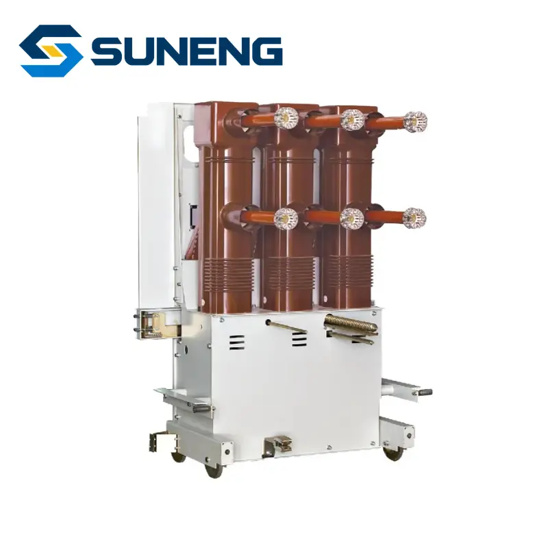
- ZN85-40.5 36kV/40.5kV Indoor Vacuum Circuit Breaker for 33kV Substation Switchgear in Africa & Middle East
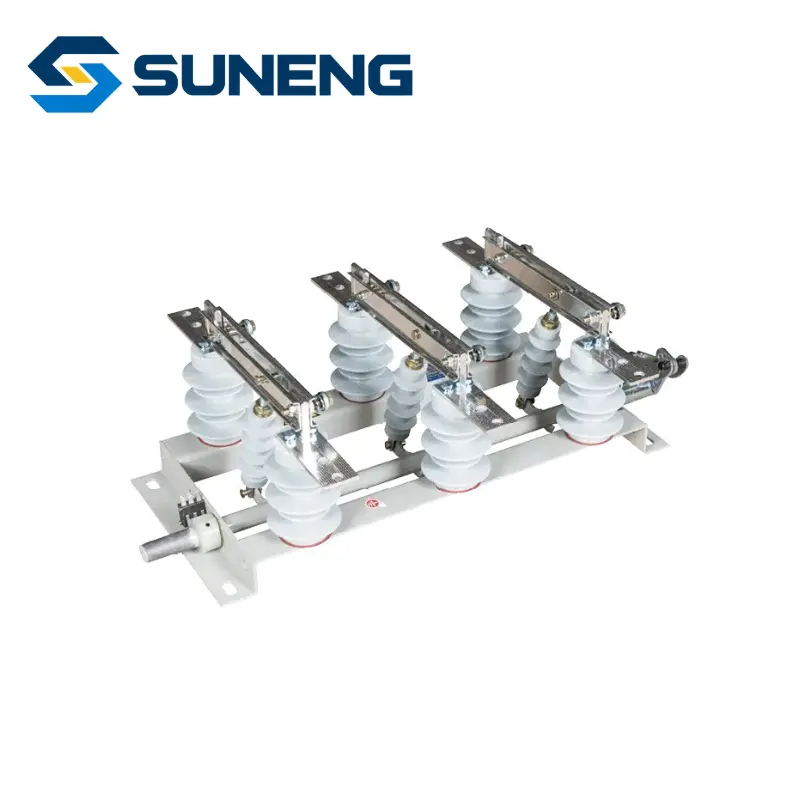
- GN19-12 type indoor high-voltage disconnect switch for Global Distribution Switchgear
SUNENG can review switchgear component and project supply requirements. Send the single-line diagram, device nameplate, interface drawing and control schematic so the proposed configuration can be checked against the actual circuit and panel.