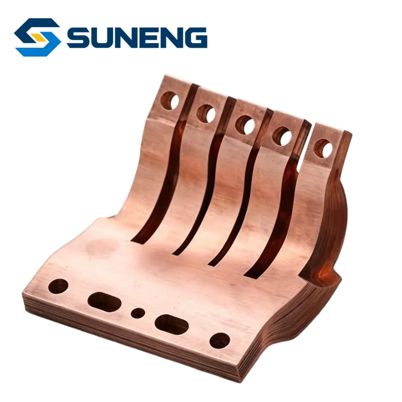
A battery cabinet may complete its initial checks, then develop a local connection hotspot after repeated charge–discharge cycles. A thicker copper bar does not necessarily address the mechanism. The joint, its restraints and its temperature history need separate attention.
Battery energy storage asks a connection to work through a changing operating profile. Load varies, enclosure conditions vary, and connected structures do not necessarily expand together. The useful reliability question is not only “Can this cross-section carry the current?” It is also “What changes at the interface after the assembly repeatedly heats and cools?”
The difference between a conductor problem and a joint problem
Distributed heating along a bar and concentrated heating at one interface suggest different investigations. If a whole current path runs hotter than the validated design predicted, review its electrical loading, cooling and installation geometry. If one joint differs from equivalent joints under comparable conditions, focus on the interface and the measurement before redesigning every conductor.
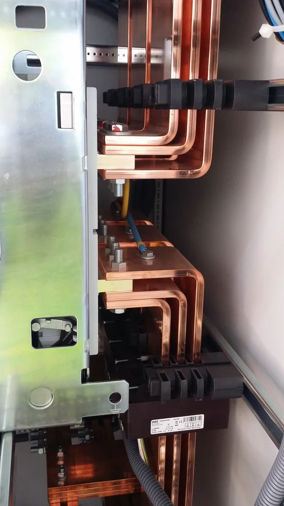
The European Copper Institute’s busbar-design guidance discusses contact surfaces, connection pressure and mechanical aspects of reliable joints.[1] This is background engineering, not evidence that any particular BESS assembly has passed a life-cycle test.
An illustrative calculation shows why the distinction matters. At 1,000 A DC, an added resistance of 10 micro-ohms dissipates I²R = 10 W. If that additional resistance became 50 micro-ohms, the local dissipation would be 50 W at the same current. These are hypothetical values, not acceptable limits. Temperature depends on where that heat goes, enclosure conditions and the surrounding structure; the calculation alone cannot predict a terminal temperature or fire risk.
Treat expansion as a load on the connection
A bar’s free thermal movement can be estimated from ΔL = α × L × ΔT. For a deliberately simplified copper example, α = 17 × 10⁻⁶/K, L = 0.5 m and ΔT = 50 K give about 0.43 mm of free expansion. That is a movement estimate, not a calculated joint force.
If both ends are constrained, the outcome depends on the complete stiffness, support locations and temperature distribution. It is therefore a mistake to use that 0.43 mm as a universal flexible-link requirement. Review which connection moves, in which direction, and whether the proposed flexible element actually accommodates that movement rather than transferring it into a terminal.
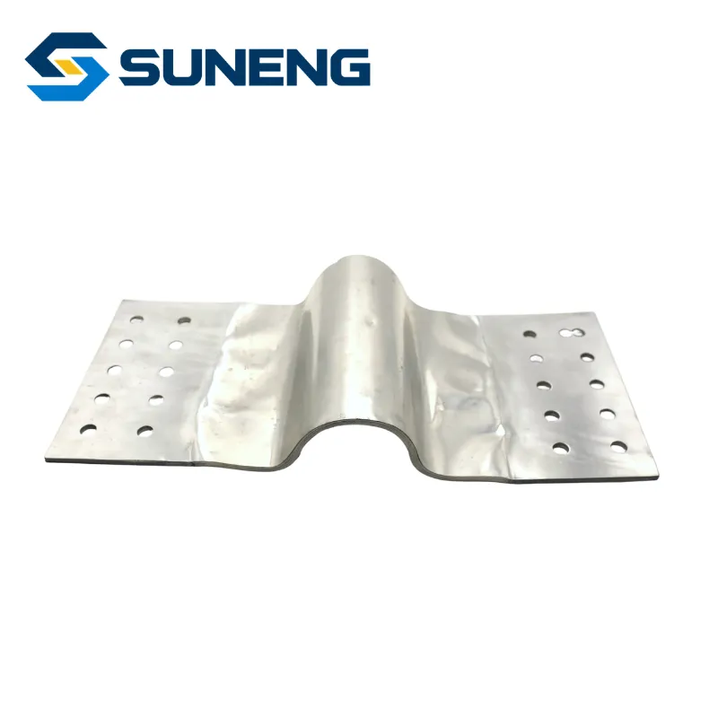
A flexible connector is not automatically a cure. Its bend orientation, unsupported length, insulation, terminal geometry and fatigue behavior still need an application-specific assessment. Conversely, a properly supported rigid connection should not be rejected just because another design uses a braided link.
Build a cycle test around the failure you need to expose
A generic “tested” label leaves several unanswered questions. Does the test article reproduce the mating terminal? Is the surface finish the same? Were the fastener stack, installation process and supports representative? How was the actual operating duty represented?
An effective validation plan names the variables and the evidence to be compared:
| Item | What to record | Why it changes the interpretation |
|---|---|---|
| Joint identity | Bar material, plating, terminal, contact area and fastener stack | A result for another interface is not a direct substitute |
| Mechanical boundary | Supports, restraint, flexible length and assembly tolerances | Cycling a free specimen may miss restraint-driven behavior |
| Operating profile | Current waveform, dwell, cooling interval and ambient | Equal peak current does not imply equal thermal history |
| Measurement method | Instrument, lead locations, temperatures and comparable conditions | Apparent drift may be caused by the measurement setup |
| Acceptance and inspection | Pre-agreed criteria, scheduled observations and teardown evidence | A final visual check alone can miss developing change |
Define the acceptance criteria with the equipment designer and applicable requirements before testing, not retrospectively to fit a convenient result. Contact resistance comparisons need a suitable low-resistance method and repeatable test conditions. This is not a recommendation to attach test leads to an operating battery system.
Do not turn a hotspot into a blind re-torque exercise
If a connection appears abnormal, first have the responsible qualified personnel determine the safe operating response. A wrench is not a diagnostic instrument. Re-torquing without investigating may obscure evidence, damage hardware or violate the assembly procedure.
During an approved de-energized inspection, preserve the record before disturbing the joint. Review the assembly instruction, fastener identity, mating surfaces, contamination, damage and support position. The torque specification belongs to that joint system; it cannot be inferred solely from bolt diameter or copied from an unrelated terminal.
Also separate resistance drift from a changed duty profile. A connection carrying a different current or sitting in a warmer cabinet is not a controlled before-and-after comparison. Compare like with like, and record what cannot be held constant.
What a useful supplier conversation looks like
Instead of asking only for a copper weight and current figure, share the movement envelope, actual terminal interface, duty profile and verification objective. SUNENG’s flexible-busbar guide covers the geometric starting point. For energy-storage copper busbars, the project discussion should extend to the whole assembled connection and its evidence plan—not imply that a component alone validates a complete storage cabinet.
The practical takeaway: assess local interfaces and repeated movement separately from bulk conductor sizing. A pass at commissioning is a baseline, not proof that the same joint behavior will persist through the operating cycle.
Source notes
[1] European Copper Institute, Copper for Busbars: Guidance for Design and Installation, David Chapman and Professor Toby Norris, February 2014. Referenced for contact and joint-design principles. The BESS diagnostic workflow, sample calculations and proposed evidence fields are original analysis, not a quoted qualification procedure or a claim of SUNENG test performance.